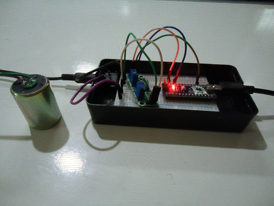
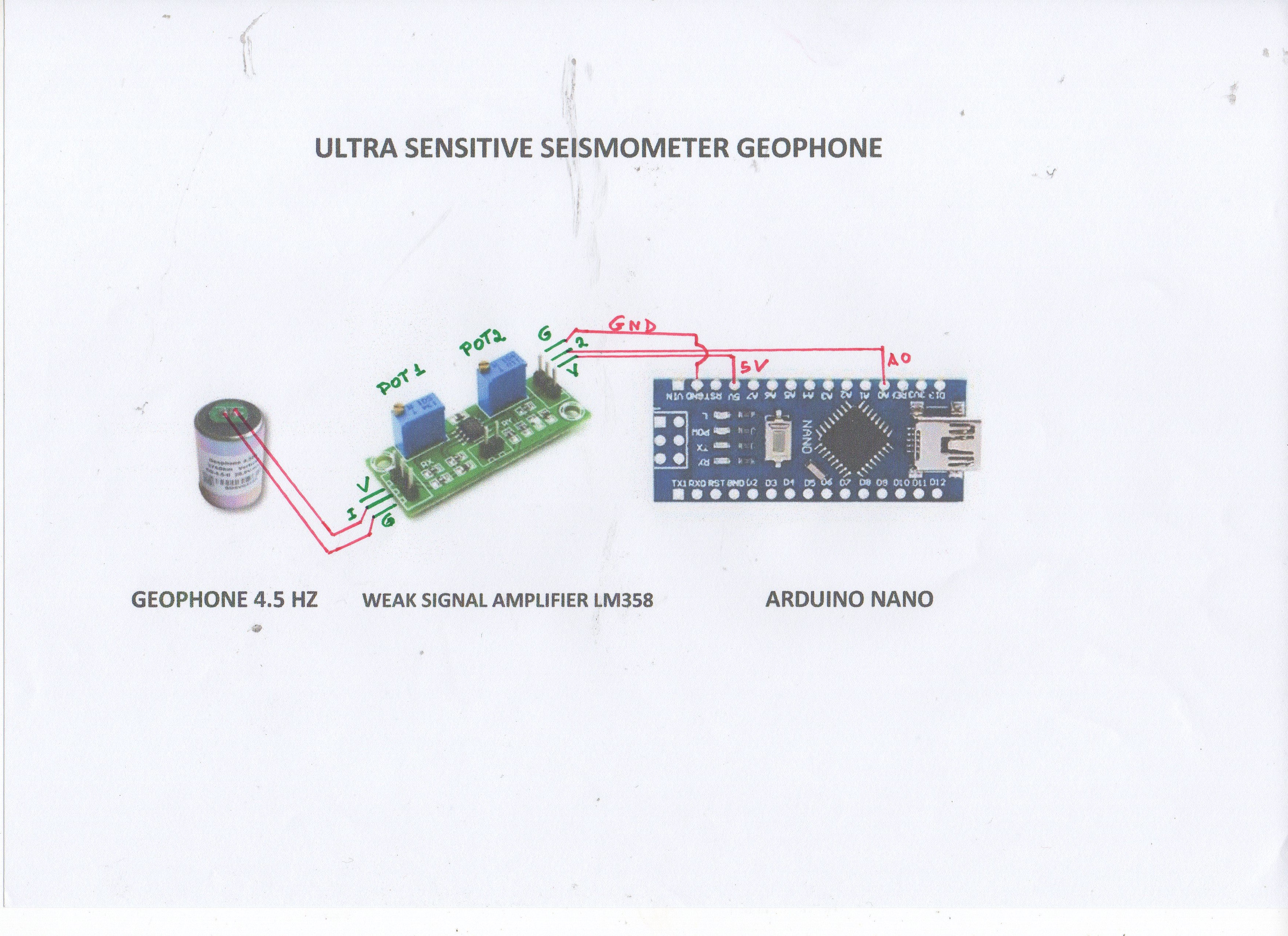
One of the biggest problems for those who make DIY assemblies of Seismometers is the amplifier of the weak signals that are generated by the Seismometer. These are very low signals that need to be amplified to be sent to the Arduino. I have already assembled several weak signal amplifiers for seismometers found on the web and practically the vast majority have a not very good gain, and besides, the difficulty to find the electronic components, mainly the ic, resistors and capacitors. After many tests I found on the market an amplifier already assembled with high gain and a very low price, it is the Dual Amplifier of Weak Signals LM358. It has two potentiometers, potentiometer 1 is 10 k ohms and potentiometer 2 is 100 k ohms. Each potentiometer has a maximum gain of 100x with the final gain being the multiplication of potentiometer 1 multiplied by potentiometer 2 with the maximum final gain being 10, 000x. Each potentiometer has 3 pins whose numbering is on the blue casing. To calculate the gain of potentiometer 1 we use a multimeter and measure the resistivity between pins 1 and 3 and the fixed value is 10 k ohms. Turning the knob of potentiometer 1 counterclockwise increases the gain. Measuring the resistivity between pins 1 and 2 and turning the knob, we would have the following values:
DUAL WEAK SIGNAL AMPLIFIER LM358
Potenciometer
Photo of the Pendulum Seismometer
0 ohms has a maximum gain of 100x
1 K ohms has a gain of 90x
2 K ohms has a gain of 80x
.....................................................
10 K ohms has a gain of 1x
To calculate the gain of potentiometer 2 we use a multimeter and measure the resistivity between pins 1 and 3 and the fixed value is 100 k ohms. Turning the knob of potentiometer 2 counterclockwise increases the gain. Measuring the resistivity between pins 1 and 2 and turning the knob, we would have the following values:
0 ohms has a maximum gain of 100x
10 K ohms has a gain of 90x
20 K ohms has a gain of 80x
.........................................................
100 K ohms has a gain of 1x
.
Photo of the Pendulum Seismometer
Amaseis software screen using a Pendulum Seismometer.
Amaseis software screen using a Pendulum Seismometer.
.I left the value of potentiometer 2 at 0 ohms which gave me a gain of 100x and I left potentiometer 1 with 7, 5 k ohms which gave me a gain of 25x, having a final gain of 2500x.
I did several tests with two types of seismometers, one of Pendulum and the other of Geophone, finding several results.
My station screen using a Geophone Seismometer on the IRIS website.
Jamaseis software screen using a Geophone Seismometer on my notebook.
The graphics inside the red window are movements of heavy cars.
I installed the seismometer in my office, which is located at a distance of 8 meters from the street lane. With a gain of 10, 000x the sensitivity of the amplifier became very strong, registering the movement of cars from distant streets as well as the steps of people inside my house. So I reduced the gain to 2500x and now only registers the movement of heavy cars and the footsteps of people inside the office. I left it like that to compare with the earthquakes in the region where I live.
The software used to record earthquakes is Jamaseis 64 bits or Amaseis 32 bits.
Realtime Image of my station on IRIS network:
https://geoserver.iris.edu/content/caru


Comments
Please log in or sign up to comment.