


Hardware components | ||||||
| × | 1 | ||||
| × | 1 | ||||
_ztBMuBhMHo.jpg?auto=compress%2Cformat&w=48&h=48&fit=fill&bg=ffffff) |
| × | 1 | |||
 |
| × | 1 | |||
Software apps and online services | ||||||
 |
| |||||
Hand tools and fabrication machines | ||||||
| ||||||
Hi there! Welcome back to this course. If you weren't here for our previous lesson(s), I strongly suggest you go back to them now, as certain parts of them are CRUCIAL for this one. But if you have done the others, I'll give you a bit of an intro to today a bit later.
Today's all about one new thing: the Joystick Module.
Modules, Modules, ModulesNow, I'd imagine that all of you have been doing Arduino for at least a week. If you've been exploring the project hub, you might have noticed one word coming up frequently. Modules. What are modules? In short, modules can do one of two things, depending on which one they are (there are more than 100 of them). Firstly, they can SENSE. This may include temperature, wetness, power, all kinds of things. If wired and coded properly, they can even transmit that signal back to an Arduino board, ready to be displayed on the screen of your computer. The other thing that modules can do is DO. Remember how in the last lesson, we used the MaxMatrix? It might surprise you, but the MaxMatrix is a module. To be more specific, it's a DO module. This is because, it doesn't sense anything, it just does something, in its case, displays a 64 segment image. Modules are a big part of Arduino, and most of them can be used without an actual Arduino board.
The module we're looking at today is the Joystick Module.
The Joystick ModuleThe Joystick Module is a SENSE module. It's basically like the joystick on a typical Xbox Controller. Let's have a look.
This on is made by Duinotech, not Sparkfun. This is the one we're going to use.
But let's have a look at what this popular module's capable of.
If you have one, move the thumbpad around it goes in circular motion but we need to quickly cover something. It's about axes. If you already know about them, you can skip this section.
AxesBy axes, I mean dimensions, almost. Here is a diagram. You might have seen these before.
The axis that goes across is called 'X'. The axis that goes top to bottom is 'Y'. So, the axes put together make grid coordinates. Go to the 3rd square on the y axis, across to the 4th square on the x axis, and you have 4, 3.
Part One: Joystick with the Serial MonitorAssemble the stuff like this.
Now that you've done that, you can paste the following code into an Arduino Ide window.
int VRx = A0;
int VRy = A1;
int SW = 2;
int xPosition = 0;
int yPosition = 0;
int SW_state = 0;
int mapX = 0;
int mapY = 0;
void setup() {
 Serial.begin(9600);
 pinMode(VRx, INPUT);
 pinMode(VRy, INPUT);
 pinMode(SW, INPUT_PULLUP);
}
void loop() {
 xPosition = analogRead(VRx);
 yPosition = analogRead(VRy);
 SW_state = digitalRead(SW);
 mapX = map(xPosition, 0, 1023, -512, 512);
 mapY = map(yPosition, 0, 1023, -512, 512);
 Serial.print("X: ");
 Serial.print(mapX);
 Serial.print(" | Y: ");
 Serial.print(mapY);
 Serial.print(" | Button: ");
 Serial.println(SW_state);
 delay(100);
}
Great. Now with that done, you can connect the Uno to the computer, and upload the code.
Now, go into the toolbar. Click on 'Tools', then, from the list that appears, select 'Serial Monitor'. A window should pop up. Wait two seconds. You should now see something like this (though the numbers will be different). 'X: 00 | Y: 00 | Button: 1'. Now, move the thumbpad on the joystick around. Whoa! The numbers change! Good job. Mission Accomplished.
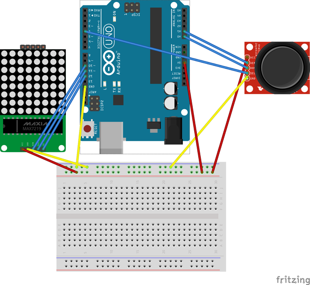
Part Two: The MaxMatrixThis part gets a slight bit trickier. If you don't want to do it, there probably won't be any new skills learnt. But if you want to, you can do it. Get out your MaxMatrix; you're going to need it. To start, assemble this.
PLEASE NOTE: This diagram shows a Sparkfun joystick. To use a Duinotech one, simply move all the wires except the red one to the right on the pins, putting the yellow one next to red. Now, go down to the Code section, and put the code there into Arduino IDE. Upload, and you will see a red dot in the middle of your matrix move the joystick and the dot moves. Wow!
This sadly brings us to the end of yet another lesson, but don't worry, they'll be more!

Comments
Please log in or sign up to comment.