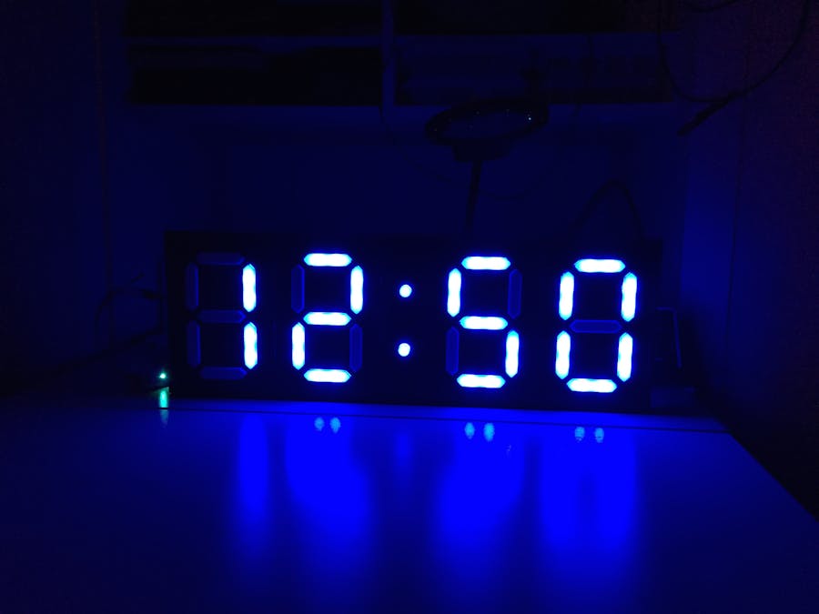
A rather large 7-segment, 4-digit clock powered by a Particle Photon. Synchronizes time with the Internet (using built-in wireless), display local (as in a sensor inside the clock itself) temperature/humidity, and display current outdoor temperature and humidity. There are a couple of different display modes (solid color, chasing rainbow), and is fully configurable via REST API. I am also working on a mobile web app for easier configuration of the clock.
InstructionsTools Needed
- Wire strippers.
- Soldering iron.
- Pencil.
- Scissors or other cutting device.
Things to Buy (if you don't own them already)
- 58 NeoPixels (10mm diameter, 5mm x 5mm LED width).
- 5v 5A power supply. (This may be optional)*
- Microcontroller (Particle Photon recommended, but an Arduino will do).
- Lots of solid core jumper wire (in spools). You'll probably want at least 3 colors.
- Solder.
- Black foamboard.
- Male-to-female jumper wires.
- (Optional) Temperature and/or humidity sensor (a DHT22 or similar).
- I am actually using a 2A USB charger, and it seems to hold up to 58 NeoPixels pretty well.
Things to Print (in ABS if you can)
- Print 4
panel-a-x4in a dark color (black recommended).
- Print 1
panel-b-x1in the same color aspanel-a-x4.
- Print 28
segment-a-x28in a light color (white or clear recommended) using supports.
- Print 2
segment-b-x2in the same color assegment-a-x28using supports.
- Print 2
frame-a-x2in a dark color (same color aspanel-a-x4, but could be something else if you want).
- Print 2
frame-b-x2in the same color asframe-a-x2.
- Print 4
frame-c-x4in the same color asframe-a-x2.
- Print 2
frame-d-x2in the same color asframe-a-x2.
- Print 4
crossbeam-x4in any color. This piece will be hidden, so the color doesn't really matter. A dark color or the same color aspanel-a-x4is recommended.
Assembly Instructions
- Fit all segments (a and b) into the panels.
segment-as will fit intopanel-as.segment-bs will fit intopanel-b. It should be a tight fit, so you may have to do some sanding. Once fitted, glue them into place using acetone (if printed in ABS) or super glue.
- Place the panels on a flat surface in the following order:
panel-a,panel-a,panel-b,panel-a,panel-a.
- Place the following frame pieces side-by-side in the following order:
frame-a,frame-c,frame-c,frame-b. Do this twice.
- Affix the frames from step #3 to the tops and bottoms of the panels by sliding the panels into the notches in the frames.
- Affix the remaining
frame-ds to the sides of the left- and right-most panels.
- Glue (or acetone weld if ABS) all the frames to the panels.
- After the glue (or acetone) has dried, orient the clock so that the open parts of the segments are facing up.
- Place the NeoPixels into the notches in the segments. Keep in mind that they are directional. I started each digit in the left notch of the center segment, went right, then down, left, up, up, right, down, then onto the next digit. When I got to the colon, I went top first, then bottom.
- Once all the LEDs are placed, start cutting, stripping, and soldering wire... this could take a while. It took me about an hour per digit. I recommend testing each digit as you finish so you can make touch-ups while the iron is still hot!
- Now that all your LEDs light up, place the clock on the foamboard and trace it. Cut out the trace, trim the edges, and put it in the back of the clock. I made sure it was a snug fit so that it would hold in place with friction.
Electronics
- Take the foamboard back out and place it on a solid surface. If you have a microcontroller with male headers (like a Photon), set it on the foamboard a few inches from an edge (and near the starting point of the NeoPixels), and give it a good press to make indentations in the foamboard.
- Remove the microcontroller and cut the indentations all the way through.
- (Optional if you want a sensor) Trace the sensor (DHT22 in my case) and cut out a square for mounting. Make sure it is well-insulated from the NeoPixels in the clock as they can put out a fair amount of heat and skew the temperature readings).
- Push the female end of the jumper wire(s) through the microcontroller slits.
- Plug the female end of the jumper wire(s) into the appropriate pin(s) on the microcontroller.
- Depending on your power source, do all that wiring now as well. If using a Photon with a beefy USB charger, you can use the VIN and GND pins to power your NeoPixels. If you use another power source, wire it to the microcontroller and NeoPixels appropriately.
- Push the microcontroller with attached jumper wires back through the slits.
- Plug in the power and prepare to program!
The Code The code I have written is for a Particle Photon or Core. It should be trivial to port it to an Arduino, or any other platform that uses Wiring / C / C++.
Source code available via this GitHub repository.


Comments
Please log in or sign up to comment.