

Hardware components | ||||||
 |
| × | 1 | |||
| × | 1 | ||||
Firstly, let's see video about the project
Hardware needed:1. Arduino Pro Mini https://amzn.to/2xy4yFn
2. Heating element (rice cooker) https://amzn.to/2N6xFoh
3. Relay 24VDC (contact 220VAC 2A) https://amzn.to/2NaPLpm
Buy electronic component on utsource.net
Software needed:1. Arduino IDE
2. Visual Studio 2008
Step 1: Temperature measurementSensor NTC Thermistor is used to measure temperature. Full instruction how to use this sensor for Arduino, pleast see project at this link
Step 2: Review hardwareBecause 220VAC is used to control heating, so it is important to make a look at Relay 24VDC and Heating element of rice cookerThe relay in this project is OMRON MY2NJ 24VDC 250VAC 5A
This means: relay's coil is controlled by 24VDC, and the contact can load up to 250VAC 5A
Model of rice cooker is Sharp KSH-218, it has 2 mode: cook and warming mode. Warm mode: heating resistance is 1.1 (KOhm); whereas cook mode has heating resistance is 80 (Ohm)"Cook mode" can generate more heating than "warm mode" -> "cook mode" is used in this projectIn "cook mode", current using is 220 (VAC) / 80 (Ohm) = 2.75 (Amp)-> this current is small enough for relay (which could load up to 5 Amp)
Step 3: Make circuitThe circuit has 2 function: measure temperature by NTC Thermistor sensor and control ON/OFF heating element by relay
The code will follow above graph:
a. When present temperature "T_present" is below "T_low limit" -> Arduino will send output command, heating will ON. Heating is keeping ON until "T_high limit"
b. Heating is OFF until "T_present" reach "T_high limit"
c. When temperature fall down to "T_low limit", heating will ON again.
This controlling pattern will help heating not ON/OFF so frequently -> can destroy relay or heating element
unsigned int ADCValue;
double temp_pv, temp_sv;
double timer1_counter; //for timer
boolean stringComplete = false;  // whether the string is complete
boolean start = false;  //start controling temperature
String mySt = "";
int delay_output;
boolean relay_on, relay_on_off;
const byte relay = 2; //relay output on Pin 2
void setup() {
pinMode(relay,OUTPUT);
analogReference(EXTERNAL);
Serial.begin(9600);
//--------------------------timer setup
noInterrupts();           // disable all interrupts
TCCR1A = 0;
TCCR1B = 0;
timer1_counter = 59286;   // preload timer 65536-16MHz/256/2Hz (34286 for 0.5sec) (59286 for 0.1sec)
TCNT1 = timer1_counter;   // preload timer
TCCR1B |= (1 << CS12);    // 256 prescaler
TIMSK1 |= (1 << TOIE1);   // enable timer overflow interrupt
interrupts();             // enable all interrupts
//--------------------------timer setup
}
void loop() {
if (stringComplete) {
// clear the string when COM receiving is completed
mySt = "";  //mySt is blank until '\n' is received
stringComplete = false;
}
//receive command from Visual Studio
if (mySt.substring(0,10) == "temp_start"){
start = true;
}
if (mySt.substring(0,9) == "temp_stop"){
start = false;
}
if (mySt.substring(0,8) == "temp_set"){
temp_sv = mySt.substring(8,mySt.length()).toFloat();  //get string after temp_set
}
if(start) //start controlling temperature - "start" command from Visual Studio
{
if (temp_pv < temp_sv - 2.0)  //on heating
{
relay_on = true;
}
if (temp_pv > temp_sv + 2.0) //off heating
{
digitalWrite(relay,0);
relay_on = false;
}
if (relay_on) relay_on_sequence();  //on heating by sequence on_off
}
else  //stop controlling temperature - "stop" command from Visual Studio
{
digitalWrite(relay,0);
}
}
ISR(TIMER1_OVF_vect)        // interrupt service routine - tick every 0.1sec
{
TCNT1 = timer1_counter;   // set timer
ADCValue = analogRead(0);
temp_pv = 0.00007*ADCValue*ADCValue-0.1849*ADCValue+103.02+2.3;

//Serial.print(ADCValue); //un-comment for calibration
//Serial.print("---");    //un-comment for calibration
Serial.println(temp_pv);
}
void serialEvent() {
while (Serial.available()) {
// get the new byte:
char inChar = (char)Serial.read();
// add it to the inputString:
if (inChar != '\n') {
mySt += inChar;
}
// if the incoming character is a newline, set a flag
// so the main loop can do something about it:
if (inChar == '\n') {
stringComplete = true;
}
}
}
void relay_on_sequence()
{
if (relay_on_off)
{
digitalWrite(relay,1);
delay_output++;
if (delay_output >= 30000) relay_on_off = false;
}
else
{
digitalWrite(relay,0);
delay_output++;
if (delay_output >= 30000) relay_on_off = true;
}
if (delay_output >= 30000) delay_output = 0;
}
Arduino will read command from PC (Visual Studio 2008) by COM Port. Then, it control temperature as above pattern.Note: because heating element is too hot, so during "ON" state, it is ON/OFF alternately to reduce heating
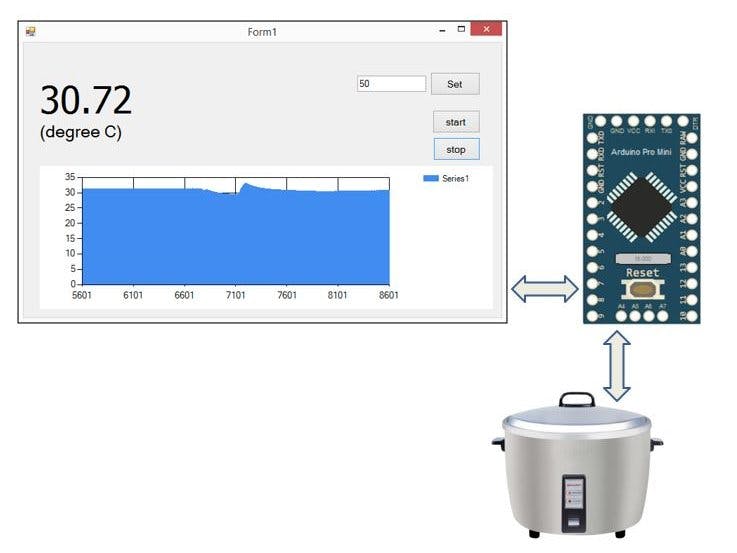
Step 5: Visual Studio 2008 codeA small HMI from PC is designed by Visual Studio 2008. It will send command to Arduino for controlling temperature, also receiving temperature from Adruino and show in graph
Main code of Visual Studio 2008
private: System::Void Form1_Load(System::Object^  sender, System::EventArgs^  e) {
serialPort1->Open();
timer1->Start();
mStr = "0";
i=3000;
}
private: System::Void serialPort1_DataReceived(System::Object^  sender, System::IO::Ports::SerialDataReceivedEventArgs^  e) {
mStr = serialPort1->ReadLine();
}
private: System::Void timer1_Tick(System::Object^  sender, System::EventArgs^  e) {
label1->Text=mStr;
this->chart1->Series["Series1"]->Points->AddXY(i,System::Convert::ToDouble(mStr));
i++;
this->chart1->ChartAreas["ChartArea1"]->AxisX->Minimum=i-3000; //shift x-axis
}
private: System::Void button1_Click(System::Object^  sender, System::EventArgs^  e) {
serialPort1->WriteLine("temp_set"+textBox1->Text);
}
private: System::Void button2_Click(System::Object^  sender, System::EventArgs^  e) {
serialPort1->WriteLine("temp_start");
}
private: System::Void button3_Click(System::Object^  sender, System::EventArgs^  e) {
serialPort1->WriteLine("temp_stop");
}
Note: to use "chart" in Visual Studio, enable it here:
Full code of Visual Studio can be found here (Google share).


_3u05Tpwasz.png?auto=compress%2Cformat&w=40&h=40&fit=fillmax&bg=fff&dpr=2)
Comments