


Hardware components | ||||||
 |
| × | 1 | |||
| × | 1 | ||||
| × | 1 | ||||
| × | 1 | ||||
This project uses L298 (known as H-bridge) to run brushless motor (taken from HDD) via Arduino Pro Mini. By this project, we also know how brushless works.
Hardware needs:
- PCB H-bridge L298 (2pcs) https://amzn.to/2QS2FeI
- Arduino Pro Mini https://amzn.to/2xy4yFn
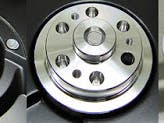
- Brushless motor (take from HDD)
Buy electronic component on utsource.net
1. Understand brushless motor principleSearching the web, we know that a brushless motor has a rotating part (called a Rotor) and has no contact with electrical wires. The main feature of this motor is that it can run with high speed. The Motor stator will create a magnetic field; when the magnetic direction is moving, it will move the rotor.
Let's see how the magnetic field is moving:
The Stator of the motor has 3 wires connected together at 1 point; the other point of the wire will connect to power source. At Phase 1, power (+) is applied to the Green coil, and power (-) is applied to the Blue coil. The sum of the magnetic field vectors of the Green coil and Blue coil will create magnetic direction as in the above picture (horizontal direction). This magnetic field will rotate the rotor and align to the magnetic direction, then stop at this direction.
To move the rotor, the magnetic field must be moving - see Phase 2:
In Phase 2, power (+) is applied to the Red coil, and power (-) is applied to the Blue coil. The sum of magnetic field vectors will create a magnetic direction as in the above picture. This magnetic field will move the rotor to this direction. Continue with phase 3, 4, 5 and 6. The magnetic field rotates 1 circle and rotor also rotates 1 circle:
A Driver for brushless motor is used to arrange power (+) and power (-) synchronizing to each coil (Blue, Red and Green) for rotating the magnetic field. T he following table summarizes the power (+) and power (-) needed to apply to each coil at each phase:
Three pairs of transistor will be ON/OFF as the pattern in the above picture to make rotating magnetic field.
3. Connection to L298 H-bridgeHalf of H-bridge is used to connect to each coil of brushless motor:
Look inside L298 IC, it is possible to flow current from half H-bridge to another half H-bridge:
- ENA IN1 is connected to H-bridge 1
- ENB IN3 is connected to H-bridge 2
- ENC IN1 is connected to H-bridge 3
This project needs 3 H-bridges and 2 L298 PCBs. Here is my result connection:
Result of connection
For this connection, we have the pattern code as shown here:
Next is coding for the above table.
5. Coding for Arduino/*
Motor - brushless motor control
Created 07 Jan. 2018
This example code is in the public domain.
http://engineer2you.blogspot.com
*/
const byte en_A = 2;
const byte in_A = 3;
const byte en_B = 4;
const byte in_B = 5;
const byte en_C = 7;
const byte in_C = 8;
int speed_motor = 20;
void setup() {
pinMode(en_A,OUTPUT);
pinMode(in_A,OUTPUT);
pinMode(en_B,OUTPUT);
pinMode(in_B,OUTPUT);
pinMode(en_C,OUTPUT);
pinMode(in_C,OUTPUT);
// start serial port at 9600 bps:
Serial.begin(9600);
while (!Serial) {
; // wait for serial port to connect. Needed for native USB port only
}
}
void loop() {
//increasing speed gradually by loop
for (int i = 0; i<=(21-speed_motor)*5; i++) {
motor_run();
}
if (speed_motor > 2) speed_motor = speed_motor - 1; //increasing speed
Serial.println(speed_motor); //print out speed to serial port
}
void motor_run() {
digitalWrite(en_A,1);
digitalWrite(in_A,0);
digitalWrite(en_B,0);
digitalWrite(in_B,0);
digitalWrite(en_C,1);
digitalWrite(in_C,1);
delay(speed_motor); //Phase 1
digitalWrite(en_A,1);
digitalWrite(in_A,0);
digitalWrite(en_B,1);
digitalWrite(in_B,1);
digitalWrite(en_C,0);
digitalWrite(in_C,0);
delay(speed_motor); //Phase 2
digitalWrite(en_A,0);
digitalWrite(in_A,0);
digitalWrite(en_B,1);
digitalWrite(in_B,1);
digitalWrite(en_C,1);
digitalWrite(in_C,0);
delay(speed_motor); //Phase 3
digitalWrite(en_A,1);
digitalWrite(in_A,1);
digitalWrite(en_B,0);
digitalWrite(in_B,0);
digitalWrite(en_C,1);
digitalWrite(in_C,0);
delay(speed_motor); //Phase 4
digitalWrite(en_A,1);
digitalWrite(in_A,1);
digitalWrite(en_B,1);
digitalWrite(in_B,0);
digitalWrite(en_C,0);
digitalWrite(in_C,0);
delay(speed_motor); //Phase 5
digitalWrite(en_A,0);
digitalWrite(in_A,0);
digitalWrite(en_B,1);
digitalWrite(in_B,0);
digitalWrite(en_C,1);
digitalWrite(in_C,1);
delay(speed_motor); //Phase 6
}

Comments
Please log in or sign up to comment.