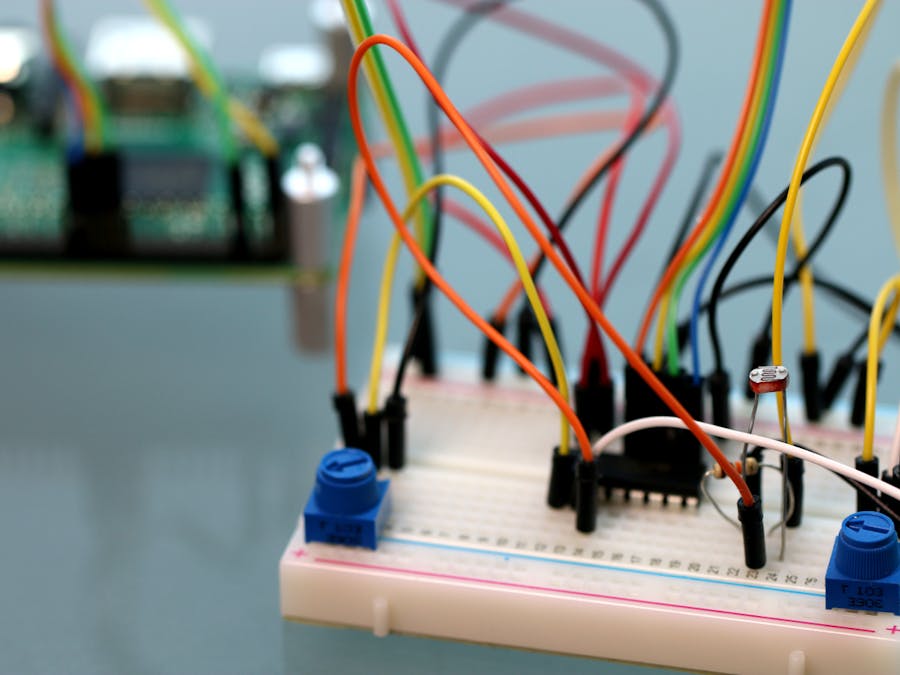
In this project we will use the Adafruit Starter Pack for Windows 10 IoT Core on Raspberry Pi 2 components to make a speaking light sensor. This will show how to use an MCP3008 Analog Digital Converter (ADC) chip to interface the Pi2 to three analog components. Two variable resistors (potentiometers) and one CdS photocell.
Note: this is a rework of the Bright or Not project which directly talked to the MCP3008 chip. That project can still be found at: https://www.hackster.io/windows-iot/bright-or-not-cc55d7
Hardware setup
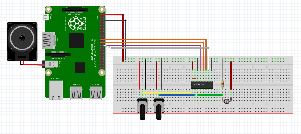
Connect the Raspberry Pi2 to the breadboard and the other components as per the Fritzing diagram bellow.
Optional
If you have a pair of headphones with a 1/8" jack or a set of powered speakers with a 1/8" jack you can connect them to the Pi2 audio output jack to hear the prompts from the speech system.
Code
MainPage.cs
You can download the code starting project from https://github.com/ms-iot/adafruitsample and we will lead you through the addition of the code needed to talk to the web service and get your pin on the map. What map?
Open up " Lesson_204V2\StartSolution\ Lesson_204V2.sln" and open the mainpage.xaml.cs file.
We have filled in a few methods as a starting point for you in this solution. If you want to jump ahead you can find a solution with all the code completed at:"Lesson_204V2\FullSolution\Lesson_204V2.sln"
Add the following lines at the top of the MainPage class.
 // Use for configuration of the MCP3008 class voltage formula
        const float ReferenceVoltage = 5.0F;

        // Values for which channels we will be using from the ADC chip
        const byte LowPotentiometerADCChannel = 0;
        const byte HighPotentiometerADCChannel = 1;
        const byte CDSADCChannel = 2;

        // Some strings to let us know the current state.
        const string JustRightLightString = "Ah, just right";
        const string LowLightString = "I need a light";
        const string HighLightString = "I need to wear shades";

        // Some internal state information
        enum eState { unknown, JustRight, TooBright, TooDark};
        eState CurrentState = eState.unknown;

        // ADC bus provider classes.
        AdcController adcController;
        AdcChannel LowPotAdcChannel;
        AdcChannel HighPotAdcChannel;
        AdcChannel CdsAdcChannel;

        // The Windows Speech API interface
        private SpeechSynthesizer synthesizer;

        // A timer to control how often we check the ADC values.
        public Timer timer;
Now add these lines to the MainPage constructor to setup the windows speech synthesizer and the ADC chip.
 // Create a new SpeechSynthesizer instance for later use.
 synthesizer = new SpeechSynthesizer();

 // Initialize the ADC chip for use
 adcController = (await AdcController.GetControllersAsync(AdcMcp3008Provider.GetAdcProvider()))[0];
 LowPotAdcChannel = adcController.OpenChannel(LowPotentiometerADCChannel);
 HighPotAdcChannel = adcController.OpenChannel(HighPotentiometerADCChannel);
 CdsAdcChannel = adcController.OpenChannel(CDSADCChannel);
Now add these lines to the OnNavigatedTo method. This will setup a timer callback which will call our code once per second on a different thread.
If you do not want to add a pin onto the map, remove MakePinWebAPICall();
 protected override void OnNavigatedTo(NavigationEventArgs navArgs)
        {
            Debug.WriteLine("MainPage::OnNavigatedTo");

            MakePinWebAPICall();
            // We will check for light level changes once per second (1000 milliseconds)
            timer = new Timer(timerCallback, this, 0, 1000);
        }
Now we have the timer callback being called lets fill it out.
 private async void timerCallback(object state)
        {
            Debug.WriteLine("\nMainPage::timerCallback");
            if (mcp3008 == null)
            {
                Debug.WriteLine("MainPage::timerCallback not ready");
                return;
            }

            // The new light state, assume it's just right to start.
            eState newState = eState.JustRight;

            // Read from the ADC chip the current values of the two pots and the photo cell.
            int lowPotReadVal = LowPotAdcChannel.ReadValue();
            int highPotReadVal = HighPotAdcChannel.ReadValue();
            int cdsReadVal = CdsAdcChannel.ReadValue();

            // convert the ADC readings to voltages to make them more friendly.
            float lowPotVoltage = ADCToVoltage(lowPotReadVal);
            float highPotVoltage = ADCToVoltage(highPotReadVal);
            float cdsVoltage = ADCToVoltage(cdsReadVal);

            // Let us know what was read in.
            Debug.WriteLine(String.Format("Read values {0}, {1}, {2} ",
                 lowPotReadVal, highPotReadVal, cdsReadVal));
            Debug.WriteLine(String.Format("Voltages {0}, {1}, {2} ",
                 lowPotVoltage, highPotVoltage, cdsVoltage));

            // Compute the new state by first checking if the light level is too low
            if (cdsVoltage < lowPotVoltage)
            {
                newState = eState.TooDark;
            }

            // And now check if it too high.
            if (cdsVoltage > highPotVoltage)
            {
                newState = eState.TooBright;
            }

            // Use another method to determine what to do with the state.
            await CheckForStateChange(newState);
        }
We have filled in most of the CheckForStateChange code for you but you want to add the call to the TextToSpeech helper method.
// Use another method to wrap the speech synthesis functionality.
await TextToSpeech(whatToSay);
Now for the fun part of the speech API, making it talk! Modify the TextToSpeech method and add these lines.
 async () =>
 {
     SpeechSynthesisStream synthesisStream;

     // Creating a stream from the text which can be played using media element.
     // This API converts text input into a stream.
     synthesisStream = await synthesizer.SynthesizeTextToStreamAsync(textToSpeak);

     // start this audio stream playing
     media.AutoPlay = true;
     media.SetSource(synthesisStream, synthesisStream.ContentType);
     media.Play();
}
MCP3008
We will now bring in the code for the Windows IoT Core Bus Provider library for the ADC Provider.
Get code
This code is located on GitHub
- Go to https://github.com/ms-iot/busProviders/
- Click Download.Zip
- Save the file somewhere easy to access (by default on windows this will be the Downloads folder).
- One the file has finished downloading open the folder it was saved into
- Extract the file (windows users can right click and Extract All..) into the Lesson_204V2 folder.
- Note the file AdcMcp3008.csproj, we will include this file into your project to bring in the bus provider code.
Add project
Now that the project code is on your machine we will go back to visual studio and add the project to your solution.
- In the solution explorer window (if not visible you can use Ctrl+Alt+L to open it)
- Right click on the name of the solution and select "Add" then "Existing Project..."
- This will open a navigation dialog for you to select the project to add.
- Navigate to the AdcMcp3008 directory you created when you extracted above.
- Select the file AdcMcp3008.csproj and click "Open"
- If you get a security warning click "Ok" to accept the warning.
Add project reference
- Now that we have the project in the solution we need to add a reference to the lesson project so that we can access that code.
- In solution explorer
- Right click on Lesson_204V2 -> References and select "Add Reference..."
- This will open the Reference Manager dialog
- Under Projects -> Solution
- you should see a line for the AdcMcp3008 project we just added.
- Click the check box and select "OK"
You can now rebuild your project and everything should be available.
Calibration
Run the code and set the breadboard in a normally lit area.
Look at the output window for the voltages being read by the ADC chip from the two potentiometers and the photo cell.
The first number is the value being read from the low adjustment pot the second is the high adjustment pot and the third is the value currently being read at the photo cell.
MainPage::timerCallback
Read values 211, 324, 179
Voltages 1.031281, 1.583578, 0.8748778
Turn the low boundary potentiometer, watching the value of the first number change. Adjust the pot until the voltage is a bit (at lease .2 volts) lower than the value of the third number.
Now turn the high boundary pot, watching the value of the second number. You want this to be a bit (once again at least .2 volts) higher than the value of the third number.
This has now configured a boundary zone where the value is "just right".
Operation
With the pots set this way if you shade the photocell with your hand the output should say "I need a light" and if you have connected the optional headphone / speaker you should hear the Pi2 speech.
Removing your shade will have it change to "Ah, just right" (and speech).
Shining a light on the sensor will change to "I need to wear shades" (with speech again).
MainPage::timerCallback
Read values 159, 324, 181
Voltages 0.7771261, 1.583578, 0.884653
MainPage::TextToSpeech Ah, just right

MainPage::timerCallback
Read values 159, 324, 149
Voltages 0.7771261, 1.583578, 0.7282503
MainPage::TextToSpeech I need a light

MainPage::timerCallback
Read values 159, 324, 372
Voltages 0.7771261, 1.583578, 1.818182
MainPage::TextToSpeech I need to wear shades
References
You can find out more about the Windows SpeechSynthesis API's at:
Information on the MCP3008 ADC chip can be found at:
http://www.microchip.com/wwwproducts/Devices.aspx?dDocName=en010530
Usage of the SPI interface:
https://msdn.microsoft.com/en-us/library/windows/apps/windows.devices.spi.aspx


Comments
Please log in or sign up to comment.