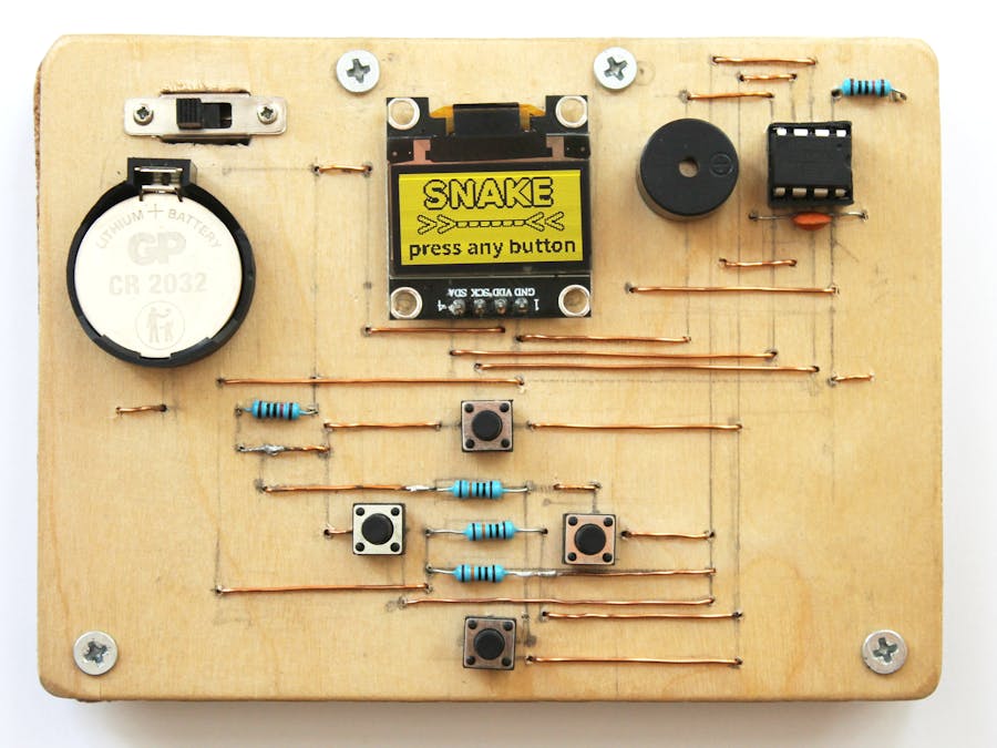
When it comes to electronics, it's the free-form designed ones that always catch my eye. Seeing how all the wires and components are connected just make it so fascinating and nice to look at. I wanted to try building something in a similar style. Being aware my soldering skills are not as good as I'd like them to be, I decided to go for a bit easier but still kind of nice-looking option. The whole build was a process of trial and error that probably cost me a bit more time than I'd like to admit. It was also the first time I ever used a ATtiny (or anything besides an Arduino Uno), which posed many challenges. But I ended up learning a lot throughout the making, so hopefully you'll do too!
PROGRAMMING YOUR ATTINY:I was using a chip without a development board, so I used my Arduino Uno as an ISP (In-System-Programmer). To keep this part of the tutorial short, I recommend you follow this article on how to do this. Please note that to make the ATtiny run at 8 MHz, you need to burn the bootloader first.
The code depends on the TinyWireMlibrary developed by Adafruit, so you need to have it in your libraries (if you don't have it already, add it in Sketch->Include Library->Add Zip Library).
The snakeGame.ino file contains the sketch you are going to upload to your ATtiny. Open it in your IDE, compile and upload. You need to have the oled85.cpp and oled85.h in the same folder as the snakeGame.ino.
NOTE: by default the display assumes a I2C address of 0x3C, in case your display uses a different one, open the oled85.h file and change the #define I2C_ADDR statement.
All source files are available on my Github.
TEST IT OUT ON A BREADBOARD:You can skip this part, but I think it's good practice to test everything before moving on to the next step. It'll be harder to identify what's not working correctly when it's all soldered together. All connections are in the schematic below:
NOTE: One issue that I encountered when building this on a breadboard was that the display had trouble rendering some frames correctly (probably due to the wonky connections). Everything worked like a charm when I soldered it together though.
PREPARING THE WOODEN BOARD:Start by cutting out two 8x11 cm plywood rectangles. Continue by grabbing some sanding paper and smoothing the surface.
Drill 4 holes at the sides of both of the boards as shown in the picture below.
Take the board that you want to use as the front side and carve out a hole for the slide switch. This can easily be done with just a sharp razor-knife.
Drill holes for the components and wires. For this, I used a 0.8mm drill bit as it was the smallest one I had. The picture below shows the layout I used, but you may need to alter it a bit based on the components you use.
Place all components and wires to their corresponding holes as in the picture below and start soldering everything together. The red lines represent the connections on the back side and the dark blue ones are the ones that are visible from the front.
Do not worry too much about how it looks from the back side, it won't be seen in the final product (just take a look at how ugly mine looks haha). I tried to solder all the wire junctions on the back, so that when I accidentally burn the wood, it won't ruin the front side.
Now try turning it on. If it works, then you did a great job. Last thing that remains is to screw the front and back side together.
NOTE: I placed a bit of cork (but you can use any other material that will do the job) between the two boards to avoid pressure on the fragile wired connections.
THANK YOU FOR YOUR ATTENTION !


Comments
Please log in or sign up to comment.