wiskey_tango_foxtrot
Published © GPL3+

PULSE Induction heater

Make heat pulses instead of heating continuously a Vapcap is the most efficient heating technique with an induction heater.

BeginnerFull instructions provided3,086
PULSE Induction heater

Things used in this project

Hardware components

A Box
×1
10K omh resistor
×1
Power cable 12V 10 A
×1
MOMENTARY SWITCH
×1
Mosfet switch
×1
Main ON-OFF Switch
×1
ZVS Module (with the coil)
×1
Arduino Nano Board
×1
Arduino nano shield
×1
DC Converter 12V to 5V
×1
Arduino cable Male to Male - Male to female
×1
Electrical wire
×1
18mm to 14mm WPA adapter
×1
Circular piece of cork
×1
Arduino prototyping square breadboard
×1
12v female adapter
×1

Hand tools and fabrication machines

Solder Iron
Double size tape
Screwdriver

Story

Read more

Custom parts and enclosures

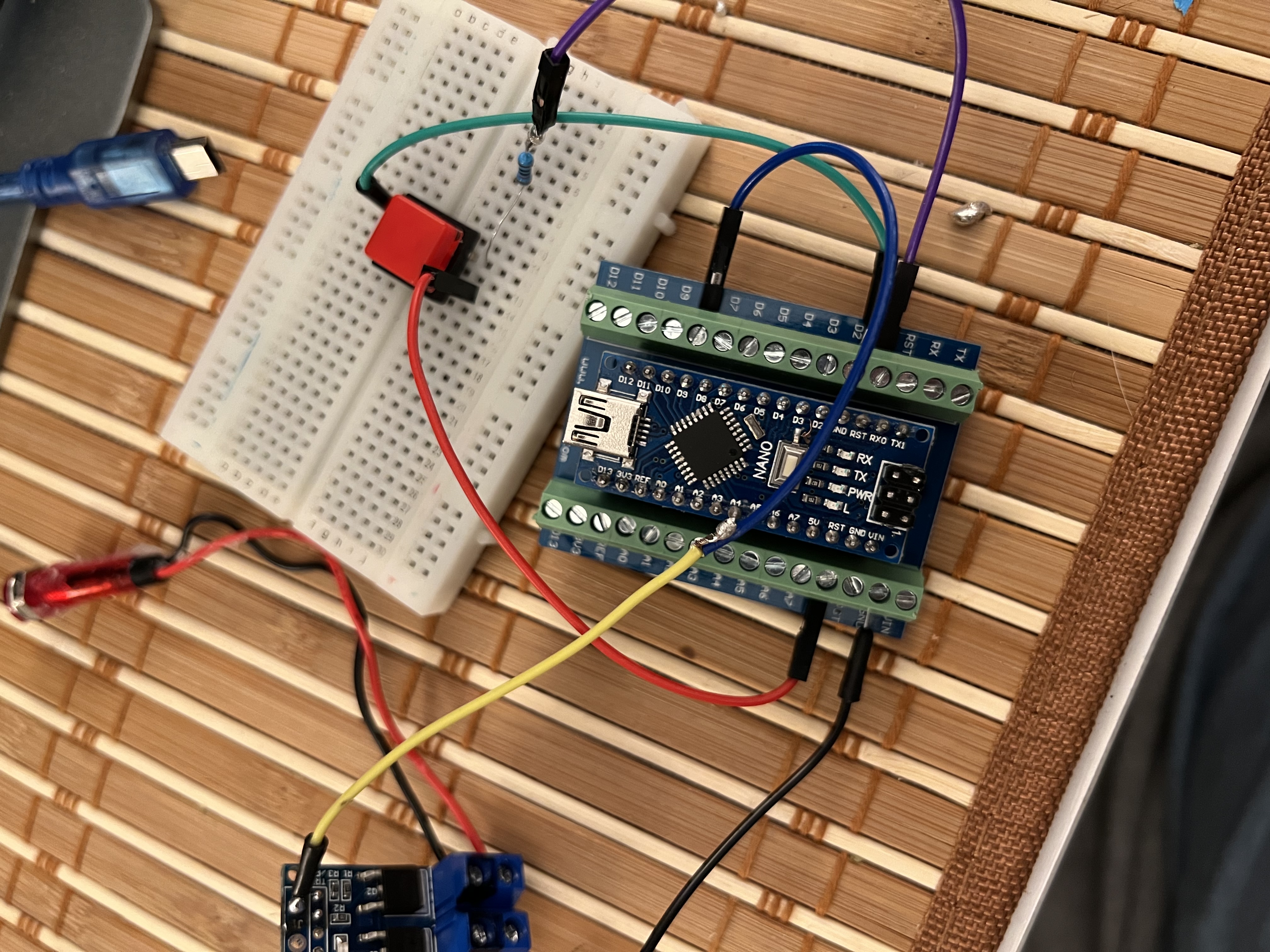
Here’s the connection between the MOSFET switch, momentary switch and Nano

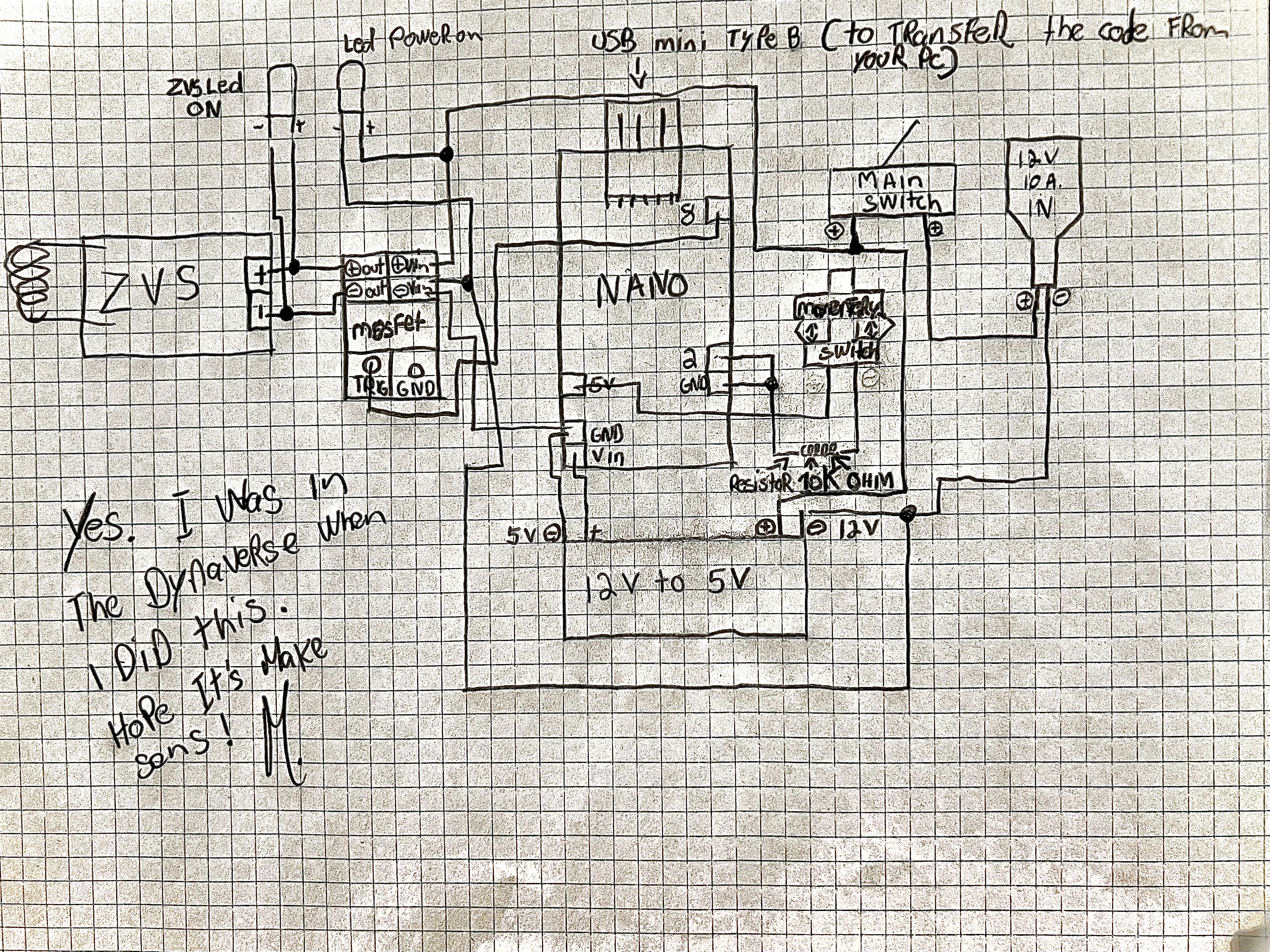
Schematics

Hardware connection circuit

Code

PULSE Script

Arduino
I made it the most simple that i could, if you’re lost, read the comment after every ‘’//‘’ they are there to guide you!
const int mos = 8;  // the pin that the mosfet switch is connected to the nano
const int Switch = 2;  // the pin that the momentary switch is connected to the nano
int switchstate = 0;  // variable for reading the button status 

void setup() {     // don't touch that!
  pinMode(mos, OUTPUT);      // initalize the mosfet switch as an output
  pinMode(Switch, INPUT);    // initialize the momentary switch as an input 
} //never remove that symbol, are you crazy!!??

void loop(){ // don't touch that! 
  
  switchstate = digitalRead(Switch); // don't touch that! 
 
  if (switchstate == HIGH) // when you press the button
    
  // this is where you can modify according to your preferences the pulse time and the waiting time between each pulse. 
 //  (1 000 milliseconds = 1 second) (500 milliseconds = half a second) (High mean ON - Low mean Off)
  
  {  
    
   digitalWrite(mos, HIGH);   
    delay(4000);               // those 4 lines represent one pulse cycle. You can ad more or less pules cycle. *if you do this its verry important to put evry cycle inside those 2 symboles: { - } + dont change the order! 
   digitalWrite(mos, LOW);
    delay(1000);
    
   digitalWrite(mos, HIGH);   
    delay(4000);                 
   digitalWrite(mos, LOW);
    delay(1000);
    
   digitalWrite(mos, HIGH);   
    delay(2000);                 
   digitalWrite(mos, LOW);
    delay(500);

   digitalWrite(mos, HIGH);   
    delay(2000);                 
   digitalWrite(mos, LOW);
    delay(500);

   digitalWrite(mos, HIGH);   
    delay(2000);                 
   digitalWrite(mos, LOW);
    delay(500);
    
   digitalWrite(mos, HIGH);   
    delay(2000);                 
   digitalWrite(mos, LOW);
    delay(500);

   digitalWrite(mos, HIGH);   
    delay(2000);                 
   digitalWrite(mos, LOW);
    delay(500);

   digitalWrite(mos, HIGH);   
    delay(2000);                 
   digitalWrite(mos, LOW);
    delay(500);

   digitalWrite(mos, HIGH);   
    delay(2000);                 
   digitalWrite(mos, LOW);
    delay(500);

   digitalWrite(mos, HIGH);   
    delay(2000);                 
   digitalWrite(mos, LOW);
    delay(500);

   digitalWrite(mos, HIGH);   
    delay(2000);                 
   digitalWrite(mos, LOW);
    delay(500);              // Important AF! the last line (mos status) before this symbole: "}" will allways be: "digitalwrite(mos, low)". if its not that, the ZVS will stay ***ON***
    
    
  } 

  else // if the button is not pressed after a cycle or when you turn the device ON, The ZVS will be off
  {
   digitalWrite(mos,LOW);
   // turn the mosfet OFF 
  }
}

Credits

wiskey_tango_foxtrot
1 project • 2 followers

Comments