Well, yeah. I play it. And you would imagine, that flying a rocket (or a plane) with a keyboard (or buttons) isn't really going to cut it. I need some sticks.
(complains about adding parts to the "components" tab in Hackster)
The amount of components available is AWFUL. None of the buttons I used (or ones that will fit) is listed, and both the ThumbPointer and SuperSlide, despite being very popular products (the RKJXV is used in PS3, PS4, PS5 & Xbox X controllers), did not even appear on Farnell.
In fact, Alps Alpine is not even listed as a supplier on Hackster. Terrible.
Also, I do not know why but the local market is literally FLOODED with these "discontinued" buttons. Literally hundreds of thousands (even millions, in the case of SKRGAED010) of units are out there, and the price is standard.
What's after these buttons? It's not as if they had made any units as replacements...
Anyhow.
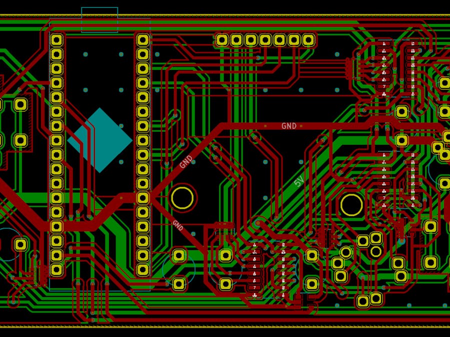
the Board24 buttons pull the pins of 74HC165 shift registers high, and the 6 banks of resistors pull them low. Then the button press is clocked in serial through the SN74AHC1G125DBVR tri-state buffer into the Arduino Micro. Then the 6 analog pins provide the analog inputs of the 6 potentiometers and finally throws all the info over to the screen (and over to the computer via USB)..
Note:
The screen (and some of the buttons/joysticks/sliders/switches) are not mandatory.
the board's first 74HC165D (at the bottom nested between two buttons) is wired to up, down, left, right, select, start, and A and X buttons. The second 74HC165 (on the top) is responsible for the four shoulders, and B, C, Y, Z buttons. The last one is responsible for the stick switch, menu, and two stick push buttons.
Assembling the boardSoldering the resistor arrays is a complete PAIN (because they are tiny, and have recess that can trap solder, which can't be reached with either wicks or solder iron tips). I barely achieved an 80% yield (12 soldered, 2 severely burned, 1 moderately burned and only 4 great). Having high-precision equipment is HIGHLY recommended, and a hot air set (with solder paste) is invaluable.
One end should all be connected together (0 ohm), while the other end should have about 2 times the listed resistance (e.g. 40k detected resistance for a 20k resistor bank). They should NOT connect.
After the resistor array comes the much easier SN74AHC1G125DBVR. Solder one of the two separate pins first, then solder the other one (on the same two-pin side). Then turn the board around and solder the last three. This prove to be the easiest module to solder.
Then you should do the 74HC165Ds. All units point upward (their "dot" side faces upward, toward the edge with the display connector and shoulder buttons).
After that, you should solder the shoulder buttons, then the regular buttons, then the RKJXM (stick-type switch), then the RKJXV(joystick), then the RS**1. Before you call it a day, you might want to solder a 1uF (label 105) ceramic capacitor on to the two pads by the buttons. Then solder the Arduino Micro (or the female headers) and the display.
When you finished soldering, you may need to wash the board (depend on the type of flux; I used some "organic acid flux" that make wonderful joints (but need to be washed off because of their slight conductivity). If you did, let it dry.
Sketches & CodeI have put together some code that allow it to function as a "USB input device".
HOWEVER, I nuked my code before I made a copy, so until I finish overhaul it, there's no code that works. But I can lead you to this article.
Well, you can throw that chunk out of the window, because I had ...well.
Between now and then I lost some progress due to "technical issues" (my old laptop became paperweight) and despite being able to recover all the data the most recent version of the code has mysteriously disappeared. Or maybe my mind was fooling me and there was never a thing called "recent version". In any case. I downloaded my previous GitHub uploads, added some changes to it, and re-uploaded it. It is there.
___
Unrelated/P.S.:
The ATmega32U4 feature 10-bit ADCs, however due to my laziness it currently has an effective accuracy of 5 bit (mostly due to me not casting to a wider type when compensating for "joystick drift"). It does not matter massively since even 16-level (32?) increment per direction is still plentiful.
How to use it (MK2_1 default sketch)I should really come up with a better name. I'll do that after I finish nuking the code completely.
Upload this XpandShield_MK2_1 sketch to the board. Power the board while keeping both joysticks centered (don't touch them). After the splashscreen, we arrive at the (only) main screen. To calibrate the joystick, move both sticks (4 channels) to the maximum allowed (not unlike in the gif), then center them again. The channels (on the screen) should be centered.
Note, that as soon as we exit the splash screen, the device will appear to the host as a "USBInput device", and thus during calibration the input is random. This is intentional.
Input bindingBoth sticks are bond to their respective channels, console style. The two inner shoulder button is Z-axis, and the two sliders are Throttle and Z-rotation respectively. The four-way button (located at the "X" on the PCB) is the first DPad, and ignores button pushes on opposite directions, while the stick switch is the second DPad. All other buttons (center push, button cluster, etc) appear as regular buttons.
The device (currently) poll at 10Hz. You can view all current input on the display.
Finish clean-up code; merging HID input class with XpandShield class
Make a XInput version (likely require external burn/flash) tool


_4YUDWziWQ8.png?auto=compress%2Cformat&w=48&h=48&fit=fill&bg=ffffff)


_Ujn5WoVOOu.png?auto=compress%2Cformat&w=40&h=40&fit=fillmax&bg=fff&dpr=2)


Comments
Please log in or sign up to comment.