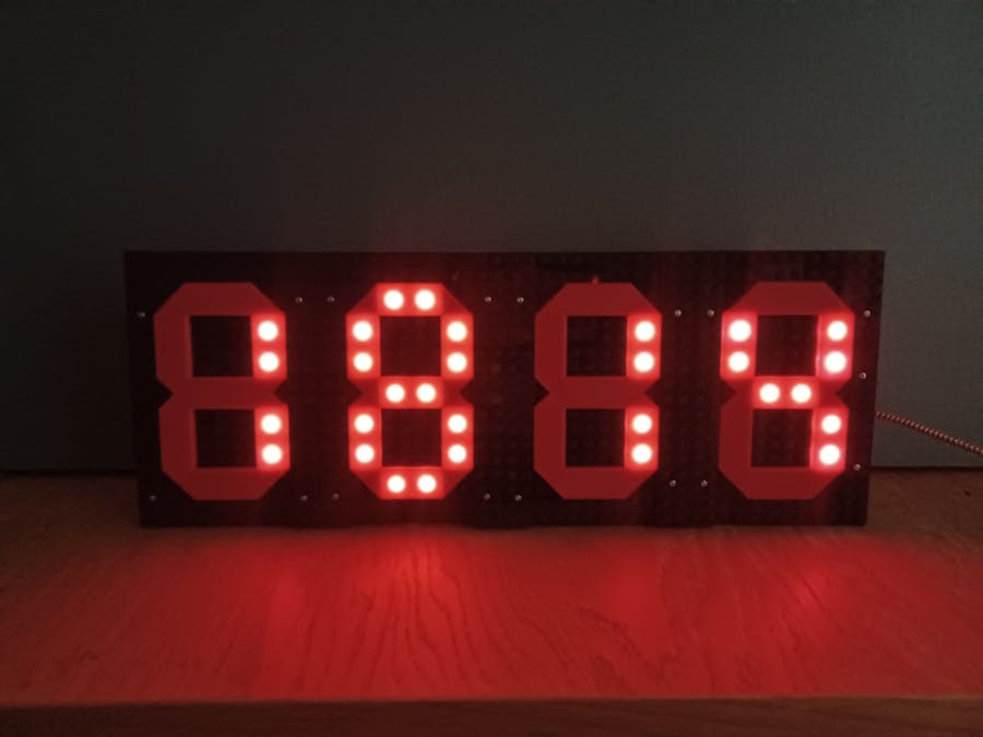
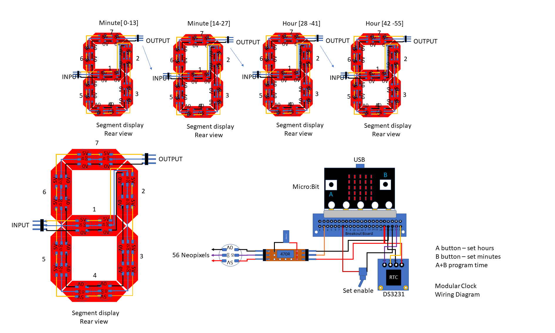
Four "Modular Display Elements" are required to create the clock display and these are held together with baseplate strips which were cut from a larger baseplate.
The schematic shows the components that are used to control the MDE's which contain 56 Neopixels.
The control components consist of a Microbit, RTC, Breakout Board, Switch and protection circuit.
The majority of the soldering is focused on the Neopixels whereas the control componets are mainly connected with jumpers.
The components are attached to a baseplate (95(W) x 128(L) mm), which is fitted to the back of the MDE's with M3 X 25mm bolts and 10mm standoffs.
Four bolts are fitted through the holes in the Neopixel support board and the standoffs fitted to attach the baseplate at the corners, 3mm holes are made in the baseplate to align with the bolts.
Position and drill holes for the Edge connector Breakout (2 x 3mm), the RTC (2 x 2mm), and the switch ensuring to leave space (20 x 40mm), to mount the right angle brackets which act as feet.
Connections to the RTC are made with 4 Junior jumpers F/F and the RTC is secured with 2 x M2 bolts.
Connections to the switch are made with 2 Junior jumpers F/M and the switch is fitted through a 5mm hole.
Connections to the CR protection circuit for the Neopixels is made with 3 Jumpers F/F and from this to the Neopixels with 3 jumpers F/M, this is attached to the board with a cable tie fed through one of the holes in the board.
Fit the angle bracket feet to the baseplate with 4 bolts. (The lower corner M3 bolts for attaching the baseplate can be used to hold the feet in place with a 2nd bolt in the lower hole of the bracket.
To prevent scratching the surface on which the clock will sit, attach stick on pads or a couple of turns of tape.
The baseplate can now be fitted on to the corner support bolts and secured with nuts.
Further information for this and related projects can be found here:


Comments
Please log in or sign up to comment.