This is a continuation of the following tutorials:
ATmega328P and its Architecture
Accessing I/O in ATmega328P using Assembly
Block Diagram of Analog Comparator:"The analog comparator compares the input values on the positive pin AIN0 and negative pin AIN1. When the voltage on the positive pin AIN0 is higher than the voltage on the negative pin AIN1, the analog comparator output, ACO, is set.
The comparator’s output can be set to trigger the Timer/Counter1 input capture function. In addition, the comparator can trigger a separate interrupt, exclusive to the analog comparator. The user can select interrupt triggering on comparator output rise, fall, or toggle." - Manual
The pins AIN0 and AIN1 of the analog comparator module are externally connected to the IO pins PD6 and PD7.
Even though AIN0 is fixed as one of the inputs, AIN1 can be varied using the ADMUX output as shown in the table below.
ACD - Analog Comparator Disable: when this bit is set by writing 1, the analog comparator is switched off.
ACBG - Analog Comparator Bandgap Select: When this bit is set, a fixed bandgap reference voltage replaces the positive input to the analog comparator. When this bit is cleared, AIN0 is applied to the positive input of the analog comparator.
ACO - Analog Comparator Output: The output of the analog comparator is synchronized and then directly connected to ACO. The synchronization introduces a delay of 1 - 2 clock cycles.
ACI - Analog Comparator Interrupt Flag: This bit is set by hardware when a comparator output event triggers the interrupt mode defined by ACIS1 and ACIS0. The analog comparator interrupt routine is executed if the ACIE bit is set and the I-bit in SREG is set. ACI is cleared by hardware when executing the corresponding interrupt handling vector. Alternatively, ACI is cleared by writing a logic one to the flag.
ACIE - Analog Comparator Interrupt Enable: When the ACIE bit is written logic one and the I-bit in the status register is set, the analog comparator interrupt is activated. When written logic zero, the interrupt is disabled.
ACIC - Analog Comparator Input Capture Enable: When written logic one, this bit enables the input capture function in Timer/Counter1 to be triggered by the analog comparator.
ACME - Analog Comparator Multiplexer Enable:
When this bit is written logic one and the ADC is switched off (ADEN in ADCSRA is zero), the ADC multiplexer selects the negative input to the Analog Comparator. When this bit is written logic zero, AIN1 is applied to the negative input of the Analog Comparator.
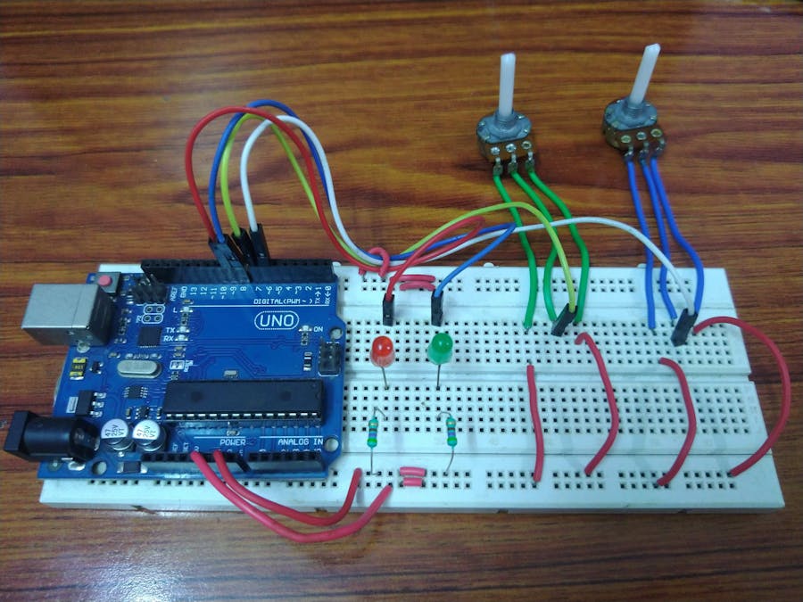
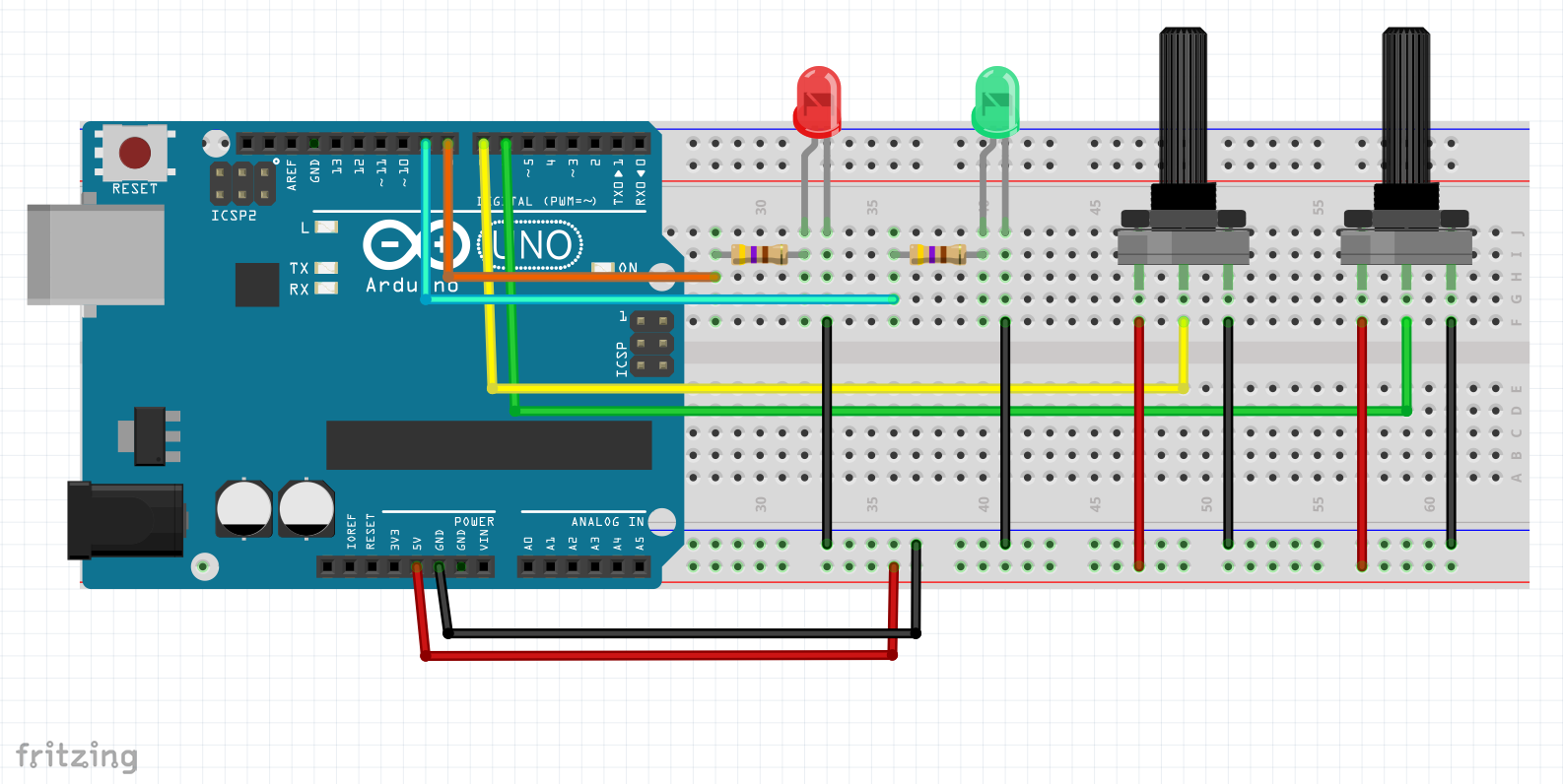
Demo:In this simple demonstration, two variable resistors are connected to the AIN0 and AIN1 pins of the analog comparator module, and when the voltage at AIN0 is greater than AIN1, LED connected to PB0 is turned ON, and LED connected to PB1 is turned OFF, when the voltage at AIN1 is greater than AIN0, LED connected to PB0 is turned OFF and LED connected to PB1 is turned ON.
Potentiometer?The potentiometer is used to give an analog input as voltage, as the resistance of the potentiometer can be varied by adjusting the sliding contact (Using the simple principle of resistance, R is directly proportional to the length of the conductor).
Determining the register values
In the same way, ADCSRB is also set to 0x00, however, it's not necessary to set it as the default value of the registers is usually 0x00.
To check the output of the analog comparator, one can read the ACO bit, i.e, bit 5 of ACSR.
For PORTB, writing 0x02 is setting the bit 1 of PORTB, and writing 0x01 is setting the bit 0 of PORTB and clearing all other bits in both cases.
Migrating to C:Coding in assembly language can be a tedious process, hence it's recommended to use the C language to code using simple bit manipulation techniques.
Here's the comparison between assembly and C:


_ztBMuBhMHo.jpg?auto=compress%2Cformat&w=48&h=48&fit=fill&bg=ffffff)


Comments
Please log in or sign up to comment.