This is a continuation of the following tutorials:
ATmega328P and its Architecture
Accessing I/O in ATmega328P using Assembly
The Timer/Counter1 module in ATmega328PThe 16-bit Timer/Counter unit allows accurate program execution timing (event management), wave generation, and signal timing measurement.
Simple delays can be produced using the timer/counter1 by writing the required delay values into the respective registers.
Registers:TCCR1A won't be of much use in this tutorial, might be useful in the next one for output compare unit in waveform generation.
This register is used to set the clock speed for the timer/counter1.
The bits we need to use are [2:0] which are the prescalars, used to reduce the clock speed by dividing it with a power of 2.
The value loaded into this register will be incremented until its maximum value, after which the overflow flag (TOV1) in TIFR1 will be set to 1 and TCNT1H & TCNT1L will be reset to their minimum value, i.e, 0x00.
To determine the value to be loaded into this register, the following formulae can be used:
The clock speed (16MHz) has to be reduced to get the overall count value less than 2^16. Thus a Prescaler of 1024 is used. Then the final delay value can be calculated using the formula for a delay of 1 second. Delay value = 49911 in decimal, converting it to hex, we get a 16-bit value of 0xC2F7, this 16-bit value should be loaded as two 8-bit values as 0xC2 in TCNT1H and 0xF7 in TCNT1L.
This register has the flags connected to different modules in the timer/Counter1
Producing a delay using the Timer/Counter1:LDI R16, 0x01
STS DDRB, R16 ; Setting 1st bit of PORTB as output
LDI R17, 0x00
STS PORTB, R17 ; Writing 0 to PORTB (LED OFF)
LDI R16, 0x00
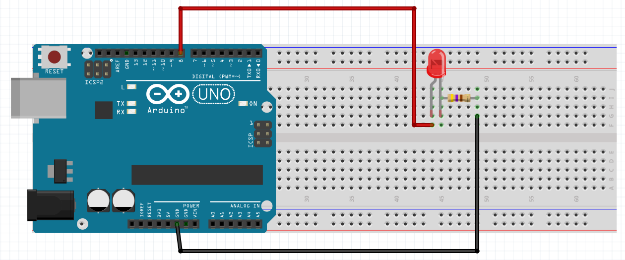
STS TCCR1A, R16 ; Setting all bits of TCCR1A as 0An LED is connected to the PB0 pin and configured as an output. All bits of TCCR1A are set to 0 as no output compare of waveform generation is used. This part will complete the setup.
The upcoming code will go into the loop segment:
LDI R16, 0xC2
STS TCNT1H, R16   ; Writing 0xC2 into TCNT1H (8-bit)
LDI R16, 0xF7
STS TCNT1L, R16   ; Writing 0xF7 into TCNT1H (8-bit)
As calculated using the formula the 16-bit value of 0xC2F7 is stored as separate 8-bit values into the upper and lower TCNT registers.
LDI R16, 0x05
STS TCCR1B, R16   ; Writing 0x05 into TCCR1B
0x05H => 0000 0101B is set as the bits for TCCR1B as no input capture is used and a Prescaler of 1024 is used, hence 101 for CS12, CS11, and CS10 respectively. The Timer/Counter1 is turned ON once the value is written into TCCR1B with the given Prescaler.
L: LDS R0, TIFR1   ; Load the value of TIFR1 into R0
   SBRS R0, 0      ; Skip the next statement if overflow has occured.
   RJMP L          ; Loop until overflow occurs.
This is a loop, used to wait for 1 second, till the overflow occurs in the Timer/Counter1. This can be done by checking the overflow flag, i.e, the 0 bit of the TIFR1 register.
LDI R16, 0x00
STS TCCR1B, R16    ; Stop the Timer/Counter1
The timer is stopped to reset the overflow flag and toggle the LED
LDI R16, 0x01
STS TIFR1, R16     ; Clear the overflow flag by writing 1 to it
COM R17            ; Complement R17 register
STS PORTB, R17     ; Toggle the LED output
This will go into an infinite loop for continuously blinking the LED.
Complete code attached in the Code Section.
The e-C way: (C code)const int LED_Pin = 8;
void setup()
{
pinMode(LED_Pin, OUTPUT);
}
void loop()
{
digitalWrite(LED_Pin, LOW);
delay(1000);
digitalWrite(LED_Pin, HIGH);
delay(1000);
}There have to be two files to code in assembly language in the Arduino IDE. One.ino file to provide the basic info to the IDE to use the assembler and one.s file which contains the assembly code.
Please note that the.ino file and the.s file have to be inside the same folder with the same name.
Congratulations! 🎉
You have successfully uploaded the assembly code into your Arduino Uno!
Output:


_ztBMuBhMHo.jpg?auto=compress%2Cformat&w=48&h=48&fit=fill&bg=ffffff)


Comments
Please log in or sign up to comment.