This December, I travelled home to Missouri to spend the holidays with my family. I was completely clueless about what to get my in-laws for Christmas and I had come home empty handed. So while I was sitting around and visiting, they happened to ask if I could run down to the basement and empty the dehumidifier. Typically, dehumidifiers have an outlet or spout to attach a garden hose so the condensation can run out into a drain. Unfortunately their model does not, so they have to keep walking up and down the stairs to the basement at least twice a day. Eureka! I realized what I could make for their Christmas present... an automated dehumidifier sump pump!!! So I raced out to RadioShack, grabbed all the parts and started off to work!
Before the water level gets high enough for the dehumidifier to turn off, I need to drain the tank, wait for it to refill and repeat indefinitely.
Turn on a pump when the water level rises above an upper threshold, then disable the pump when the water level drops below a lower threshold.
Now, how do I establish the thresholds? Water (unless distilled) has the ability to conduct electricity. Theoretically, I could twist two pairs of wire to different lengths, and determine the presence of water based on a short across either pair. Unfortunately, water makes a lousy conductor, so there will be losses in voltage that need to be reconciled in order to measure the presence of the short. Fortunately, we have transistors to do just that, and what's more, we have a Darlington pair, which is a double dose!
NOTE: A transistor consists of three parts, a collector (input), emitter (output) and base (valve). When current is applied to the base, it lowers the resistance between the collector and emitter and allows current to flow from the collector to the emitter. The more current applied to the base, the more current that flows from the collector to the emitter, producing what is known as the current gain or amplification factor of the transistor. Then when you double them up, and direct the output from the emitter of one transistor into the base of another, Viola!, you get a Darlington pair.
Now that I have a way to detect the presence and depth of the water, I need a way to turn on and off a pump. The pump is a simple device, it just plugs into the wall and runs. I need a way to effectively plug-in and unplug the pump. A relay provides the ability to switch high voltage and current from logic level voltage and current. I can put the relay inline with an extension cord and use it as a logic driven power switch.
Finally, I need the logic. This is a no brainer - the Arduino UNO. It's cheap, readily available and can easily be programmed to read the water sensor and trigger the relay.
http://www.learningaboutelectronics.com/Articles/What-is-hfe-of-a-transistor
I have my plan in place, now it's time to breadboard my solution!
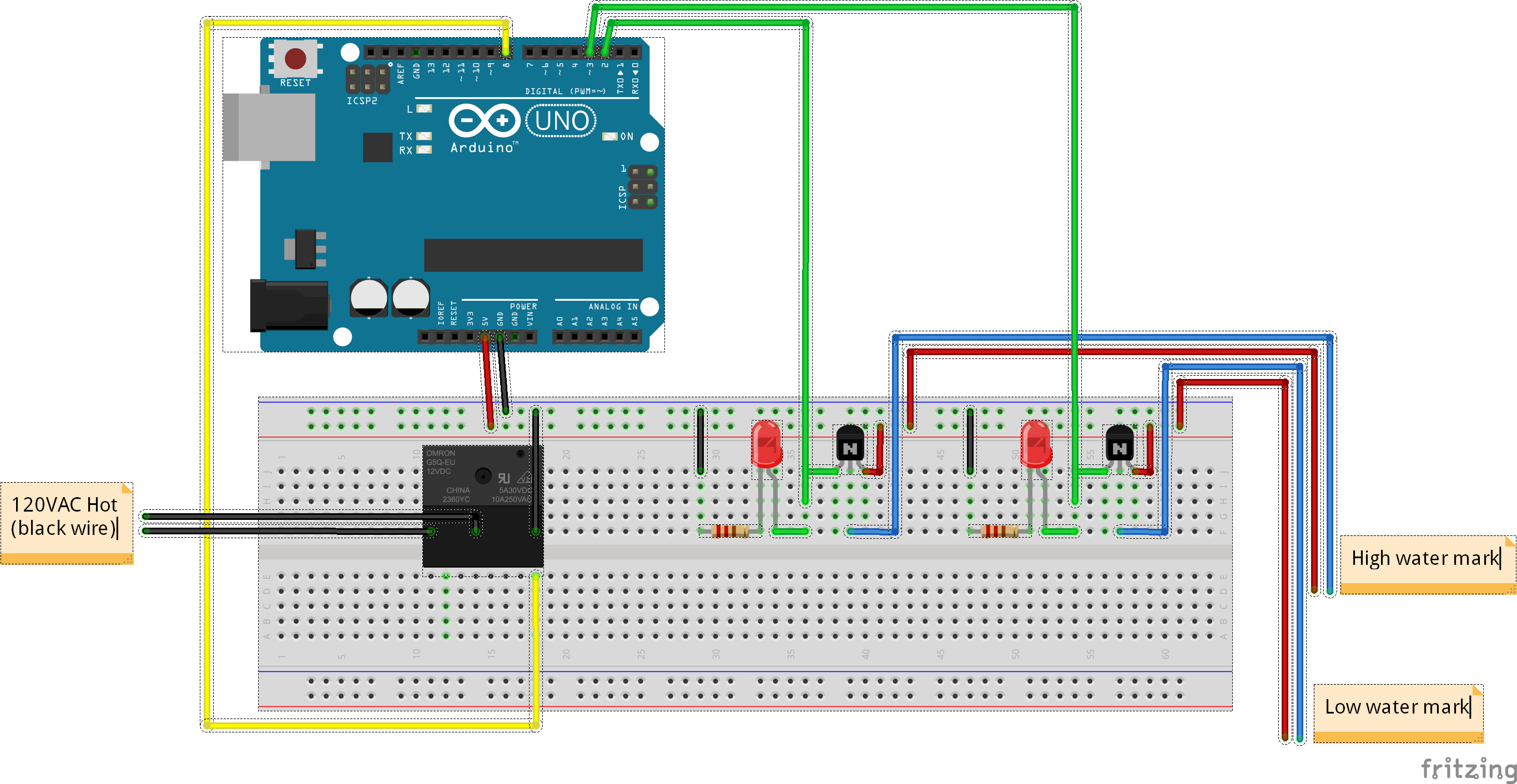
I started by wiring up the water detector circuit. First, connect the wires that will be going into the water to 5V0. Next, wire up the transistors. Connect the collectors to 5V0, the bases to the wires that will be returning from the water, and the emitters to pins 2 and 3 of the Arduino. Finally, add status LEDs. Connect the anode (positive or long leg) of the LED to base of a transistor. Then, connect the cathode (negative or short leg) of the LED to one end of a 100Ω resistor and connect the other end of the resistor to ground.
NOTE: Be sure to pull up the datasheet and confirm you wired up the legs correctly. I ended up wiring mine backwards on my first try; save yourself the headache. ;-)
Next, I tested my relay circuit. The "coil" is effectively the switch and is bidirectional, so hook one end to ground and the other up to pin 8. You want to splice the higher voltage that you will be switching into the COM (common) pin and out of the NO (normally open) pin on the relay.
Now it's time to solder it into the proto board and make a shield for the Arduino!
To finish the controller, add the project box to protect the new pump controller. I used metal files to grind away the box just enough for the cable to fit. There is a natural collar on the plug end of the extension cord, so this does a great job of protecting the shield from being jerked around by the cord. However, the other end is vulnerable. As you can see below, I used a zip tie to protect the other end from being pulled out.
The final step is to add the pump. Affix the water detector into a position where the lower detector is above the intake for the pump and the upper detector is below the shutoff switch for the humidifier. WARNING: The position of lower detector compared to the pump intake is very important. The pump will be ruined if it sucks in air instead of water for a prolonged period of time. Lastly, route your hose wherever it needs to go, even uphill!


.jpg?auto=compress%2Cformat&w=900&h=675&fit=min)
_ztBMuBhMHo.jpg?auto=compress%2Cformat&w=48&h=48&fit=fill&bg=ffffff)


Comments
Please log in or sign up to comment.