I was inspired to build this device by a home assignment on Digital Signal Processing online course. This is a DTMF decoder implemented with Arduino Uno and in this article I’ll explain how it works.
In DTMF each symbol is encoded with two frequencies according to the table
The device captures input from the microphone and calculates amplitudes of eight frequencies for further analysis. Let’s consider the algorithm in greater details.
Data acquisitionIn order to perform spectrum analysis samples should be captured at a certain predictable frequency. To achieve this I used free-run ADC mode with maximum precision (prescaler 128) it gives sampling rate 9615Hz. The code below shows how to configure Arduino’s ADC.
void initADC() {
  // Init ADC; f = ( 16MHz/prescaler ) / 13 cycles/conversion
  ADMUX  = 0; // Channel sel, right-adj, use AREF pin
  ADCSRA = _BV(ADEN)  | // ADC enable
           _BV(ADSC)  | // ADC start
           _BV(ADATE) | // Auto trigger
           _BV(ADIE)  | // Interrupt enable
           _BV(ADPS2) | _BV(ADPS1) | _BV(ADPS0); // 128:1 / 13 = 9615 Hz
  ADCSRB = 0; // Free-run mode
  DIDR0  = _BV(0); // Turn off digital input for ADC pin
  TIMSK0 = 0;                // Timer0 off
}
And the interrupt handler looks like this
ISR(ADC_vect) {
  uint16_t sample = ADC;samples[samplePos++] = sample - 400;

  if(samplePos >= N) {
    ADCSRA &= ~_BV(ADIE); // Buffer full, interrupt off
  }
}
After collecting samples I calculate amplitudes of 8 frequencies encoding symbols. I don’t need to run full FFT for this, so I used Goertzel’s algorithm.
void goertzel(uint8_t *samples, float *spectrum) {
  float v_0, v_1, v_2;
  float re, im, amp;

  for (uint8_t k = 0; k < IX_LEN; k++) {
    float c = pgm_read_float(&(cos_t[k]));
    float s = pgm_read_float(&(sin_t[k]));

    float a = 2. * c;
    v_0 = v_1 = v_2 = 0;
    for (uint16_t i = 0; i < N; i++) {
      v_0 = v_1;
      v_1 = v_2;
      v_2 = (float)(samples[i]) + a * v_1 - v_0;
    }
    re = c * v_2 - v_1;
    im = s * v_2;
    amp = sqrt(re * re + im * im);
    spectrum[k] = amp;
  }
}
This is how digit 3 looks like encoded with DTMF
The rest of the code is pretty straightforward, full code can be found here. Let’s move on to building the device.
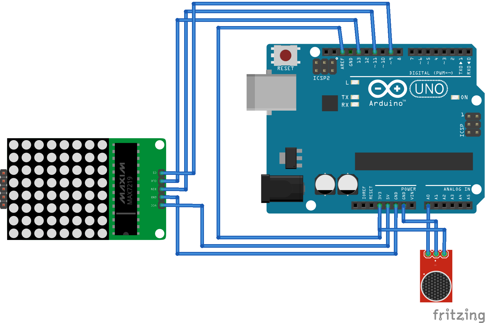
SchematicsI used the following components:
- Arduino Uno
- Electret microphone
- 8x8 LED Matrix with MAX7219 driver
The video below shows how it works
ConclusionWhat could be improved here? I used N = 256 samples at rate 9615Hz which has some spectrum leakage, if N = 205 and rate is 8000Hz then the desired frequencies coincide with discretisation grid. For that ADC should be used in timer overflow mode.


_ztBMuBhMHo.jpg?auto=compress%2Cformat&w=48&h=48&fit=fill&bg=ffffff)


_1x_bGT19vVAby.png?auto=compress%2Cformat&w=40&h=40&fit=fillmax&bg=fff&dpr=2)
_3u05Tpwasz.png?auto=compress%2Cformat&w=40&h=40&fit=fillmax&bg=fff&dpr=2)
Comments
Please log in or sign up to comment.