Some time ago I was working on an inverted pendulum project. I had trouble stabilizing it using stepper motors, however, I liked the idea of producing a force with an open-loop (no encoders needed), it simplified a model quite a bit. That time I ended up using a DC-motor with an encoder but numerous examples of a balancing robot with stepper motors inspired me to continue working on it.
In this article, I'll outline the main issues I faced working on the project, hope this will be useful in your future projects and you'll learn something new.
ModelingI thoroughly described the model and the simulation in my article @Kaggle. I prefer to simulate the system before I build it and tune the parameters in a safe virtual environment.
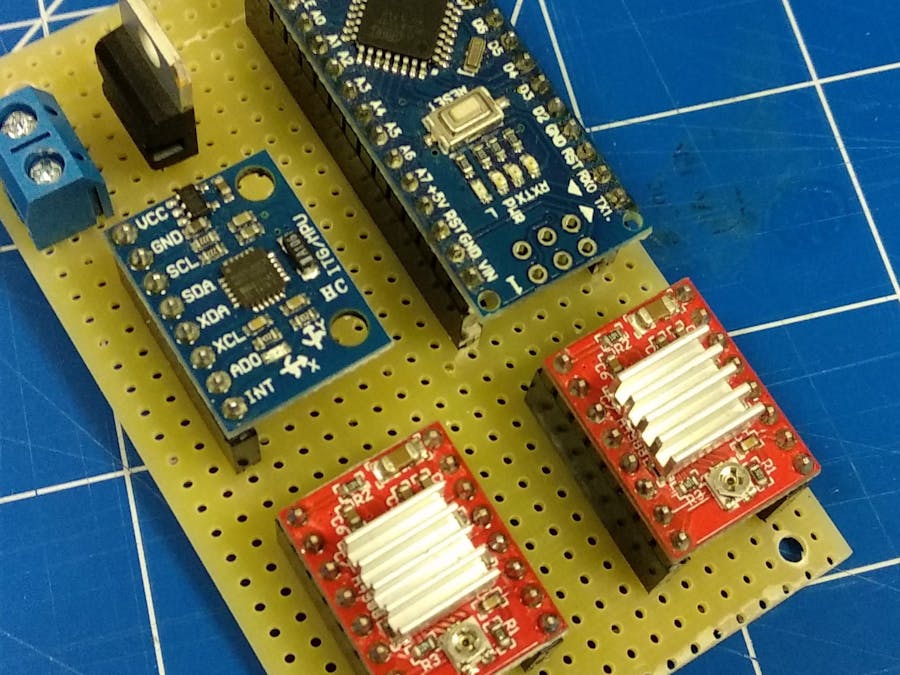
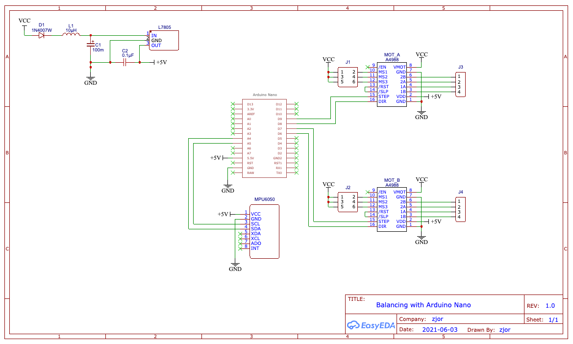
Choice of equipmentSo far I ended up with the following setup:
- Arduino Nano, 16MHz, I tried to squeeze as much computing power as possible, I'll probably replace it with the BlackPill (100MHz) or ESP32 WROOM (80-240MHz). As we'll see later, frequency matters.
- 2 Nema 17 stepper motors
- 2 A4988 stepper drivers
- MPU6050 - gyro and accelerometer with DMP on-board, also tried with the more advanced chip: MPU9250, but I didn't find good library support yet
I used 2 embedded PID control loops, one for holding the upright position and another for stabilizing velocity or position.
Velocity stabilization
Positionstabilization
Stepper control
The robot balances itself by applying a force that is roughly proportional to the angle. It means the motors should turn with acceleration. Since we have stepper motors, we need to calculate the next step delay ideally after each step (or as fast as possible). But the step itself should be precise in time, so I used a timer interrupt to make steps and 40kHz frequency (tried with 8kHz up to 100kHz, works fine but it eats CPU cycles and the control is not very smooth). This routine should be as fast as possible and should not contain any floating-point calculations.
Velocity update
The next time-sensitive task is to update the velocity and recalculate the step delay, this should be run faster than the measurement routing, otherwise, the "force" will not have enough time to act and to have an effect.
Control loop
This routine is responsible for reading the IMU (MPU6050), calculating necessary control signal, e.i. acceleration for the velocity update loop.
Using DMP
The DMP (digital motion processor) handles merging the data from the gyro and the accelerometer and gives you nice and smooth yaw-pitch-roll data. It offloads the slow CPU of the Arduino, in practice, I got x5 faster main loop after switching to using DMP compared to a hand-written complementary filter.
Final videoThe future of the projectThanks for reading up until this section, I'll share my plans for improvements and development and maybe you'll want to join this initiative.
- Use a more powerful CPU (BlackPill, ESP32)
- Add remote control via WiFi or BLE or nRF24L01
- Make an education kit, easy to assemble and understand
- Turn this robot into a platform with an API, so it would be possible to mount other equipment on it
- Another description of the project: https://hackaday.io/project/180126-self-balancing-robot-for-humans


_3u05Tpwasz.png?auto=compress%2Cformat&w=40&h=40&fit=fillmax&bg=fff&dpr=2)

Comments
Please log in or sign up to comment.