Zachary Mankowitz
IntroductionLet’s describe the problem this invention was designed to solve: for many years, I have been plagued by my siblings unlocking my locked door and sneaking into my room to take my things. The door lock is designed so it can be opened from the outside with a coin. I needed something that wouldn’t allow my siblings to unlock my door and a key that only I would have access to. It is with these goals I set out building my project. (Of course, this project can be applied in real security facilities too).
OverviewTo tackle the locking issue, I superglued a custom designed 3D printed servo mount on the inside door knob that directly interfaces with the locking mechanism. Since servo motors are constantly trying to stay in a set position, it actively pushes against any outside lockpickers. A button on the inside door acts as a toggle that can lock and unlock the door by changing the servo position.
With the locking issue solved, we need to advance to the next issue: a key that I have that no one else has. The solution to this is a fingerprint scanner. Fingerprints are something unique to each person and are something that I always have but yet can’t be taken from me. Therefore, I installed an optical fingerprint sensor on the outside of the door that can also toggle the locked versus unlocked position of the servo.
Now, we have a functioning core of a system. To enhance the system, I’ve also installed a small OLED display on the outside of the door to show the system’s status (i.e. unlocked/locked). Lastly, I added an RGB LED strip surrounding the outside door frame as an additional status indicator.
The whole system is run with dual Arduino Unos and powered by portable battery packs. Having them run off battery enables the system to keep running even during a black out.
UsageFrom outside the door, a person is greeted with a fingerprint sensor and a display saying if the door is locked or unlocked. Whenever the system is at rest, the RGB LEDs are randomly fading through 16.8 million colors. If an incorrect finger is placed, the LEDs angrily flash red and the OLED displays “Incorrect Finger”. If the correct finger is placed, the LEDs cheerfully light up green, the door unlocks, and the display welcomes you in. From inside, you can press the reset pin on the Arduino to lock or unlock the door. Whether from the inside or outside, whenever the door is locked the LEDs turn red and whenever the door is unlocked they turn green.
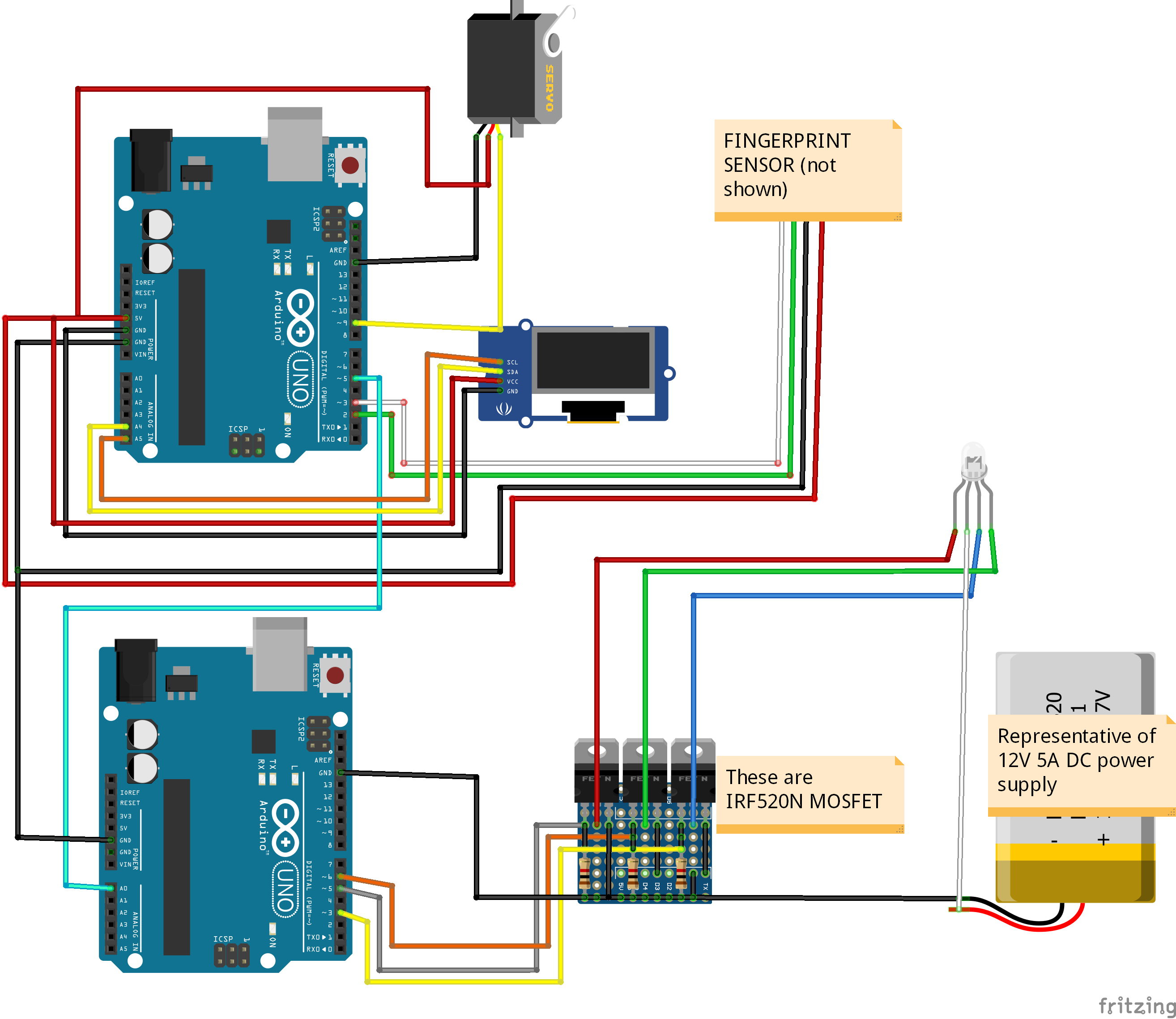
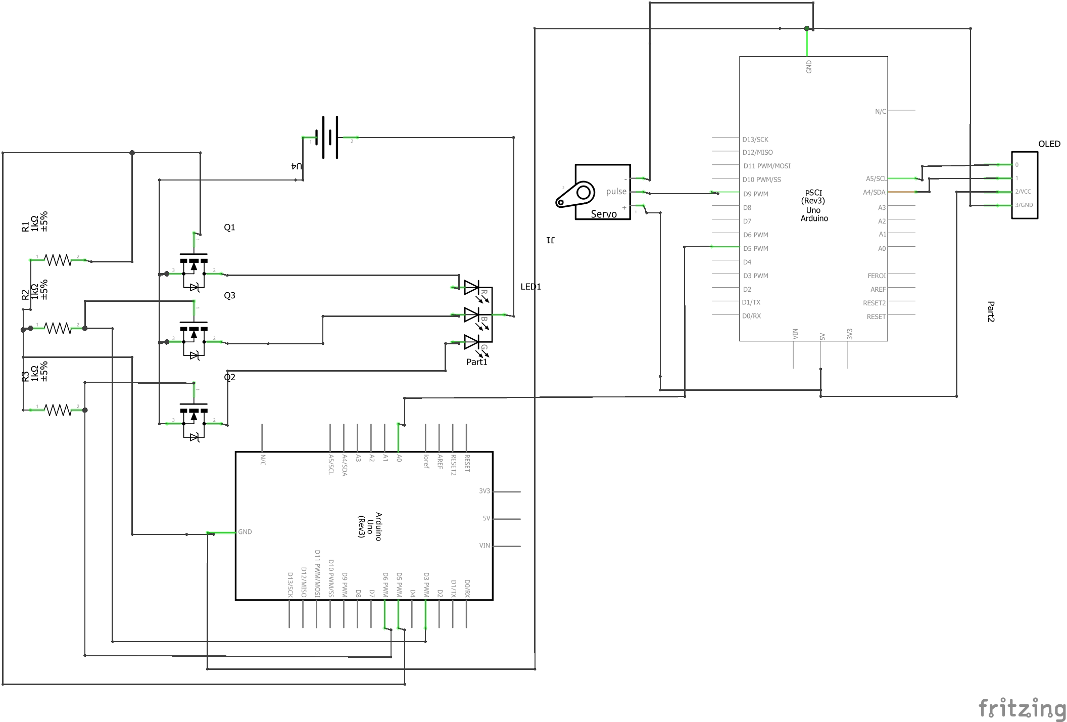
SpecificationsThis project used extensive electrical design so the following diagrams and designs are meant to help understand and design this and future systems. The code for this project was 350+ lines and can be found here. As a firm believer in open software and helping others, all resources used in this project are open to the public and can be found here. The reason there are two Arduinos is because since an Arduino can only run linearly and only has one processing core, it couldn’t control the LEDs in addition to the fingerprint sensor because they run at the same time. Therefore, there is one master Arduino which controls the Servo, OLED, and fingerprint sensor while a slave Arduino controls the LEDs. They are connected through a single wire that goes from a PWM (Pulse Width Modulation) enabled pin on the master to an analog pin on the slave. Using PWM, the master can send different voltages to the slave. Depending on the voltage, the slave will command the LEDs to run a certain mode (ex 0v to turn off, 1v to flash red, 2v to turn green, etc).
The LED’s run at 12 volts, 5 Amps - well over the internal Arduino limit (which is around 5v and 40mA). We need an interface that can handle higher DC power in order to control the LED. To do this, we use what is called a logic level Metal–Oxide–Semiconductor Field-Effect Transistor, or MOSFET for short. This has three pins: a drain, signal, and source. The signal is a voltage from 0-5v that controls the amount of flow between source and drain (usually up to 60v, 10A but depends heavily on use case. Thisis a control sheet for 520N MOSFET). Because there are three wires for red, green, and blue, there are three distinct MOSFETS for each color. Each MOSFET has an individual PWM for its signal. Since the Arduino can write 0-255 values, ranging from 0-5 volts, to each MOSFET, we have 2563 = 16, 777, 216 different possible colors combinations.
This is the 3D model mount for the servo along with the interface. The light blue object at the bottom is a 9g servo motor. The deeper blue above that is called a servo horn and gives the servo more leverage when attached. The servo screws into the white/green base. The base has four points of contact to be glued to the knob. The white piece at the top interfaces with the locking pin and is connected to the servo horn.
This is what the system looks like in person as well as a schematic view:
This is a schematic of the system except without the fingerprint sensor
Top right is a custom solderboard which holds all the MOSFETs and wiring for them together. The top left is the solderboard connected to the system. Bottom left is exterior picture of the fingerprint sensor as well as OLED display
RGB Exterior - shows LEDs at different colors


_ztBMuBhMHo.jpg?auto=compress%2Cformat&w=48&h=48&fit=fill&bg=ffffff)


Comments
Please log in or sign up to comment.