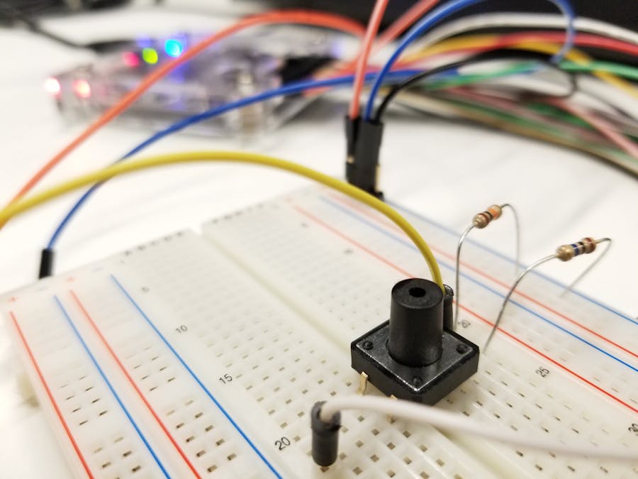
Any system that involves button presses faces the common issue of button and switch "bounce". This term refers to the fact that when a circuit element causes part of a circuit to close, a short period of signal instability will follow. The signal might oscillate around the expected level, possibly dropping below logic thresholds.
Depending on how a system is being employed, this behavior can causes all sorts of issues. Imagine trying to key in a security code that enters the incorrect combination, or a keyboard that types multiple of the same letter each time you press it.
The process of accounting for and ignoring the transition noise associated with switch changes is called "debouncing". Debouncing can be achieved in a multitude of ways, but the first step is figuring out what parameters you're working with. Knowing the typical bounce time and levels can provide insight into how the algorithm will need to operate.
In the image above, a 3.3V logic signal (yellow) is being transmitted through a push-button. The button press is initially very clean, with little noise, but after about 250µs it momentarily drops down to 200mV before stabilizing again. In 3.3V logic anything under 800mV is considered low, so a digital system without a debounce algorithm would have been registered this as two presses (expressed as Push 1 and Push 2).
Typical debouncing solutions involve waiting a certain period of time after a press is made before registering it as a press. A period of 10ms is normally more than sufficient, and human beings perceive this amount of time as instantaneous, so lag will not be noticed. However, sometimes systems need to operate at faster rates than this, so the solution is application specific.
In this case, simply waiting 500µs after the initial rise before registering the press would properly ignore the noise.
If you'd like to get some ideas about how to implement this information into an actual circuit, check out this Arduino Button Troubleshooting project.
Button or switch characterization circuitIn order to characterize buttons and switches, you'll need to build a simple circuit with the DC input signal on one side, and the oscilloscope wire on the other. (Be sure to connect the negative oscilloscope wire to ground.) The basic layouts for push-buttons and slide switches can be seen below.
If you're using a 4-pin push-button such as the one suggested in the items list, the pin-out is most likely the one shown below.
The following operations can be performed with any oscilloscope/function generator module from Digilent, including the Analog Discovery 1 & 2 modules, and the WaveForms 3 software. However, this tutorial will be done using the OpenWave module and WaveForms Live platform. Follow tutorials found in the links to set up your systems and familiarize yourself with the interfaces.
Once you've attached the DC output and oscilloscope wires, you'll need to set up the software to trigger the oscilloscope at the rising edge of the signal. When the button is pushed, the oscilloscope will see a rise in voltage and begin recording the data.
In WaveForms Live, set the level for the trigger to something sufficiently large so the oscilloscope doesn't trigger due to ground noise. A value over 500mV should be enough.
Set the time range to cover approximately 500µs (-250µs to +250µs) for buttons. The switches required a larger time range, about 2000µs (-1000µs to +1000µs).
Both the voltage and time values will need to be changed if you find that you have more noise or that there is bouncing for longer or shorter periods.
Press the Single button to arm the oscilloscope, and push the button or flip the switch. After a moment you should see the resulting waveform, similar to the image at the top. If you've successfully captured a waveform but don't see any bouncing, it's possible you'll need to perform a series of presses to get a good idea of the button's behavior. You can set the oscilloscope to run continuously by pushing the Run button. It will still be triggered on the rising edge of 500mV. This way, you'll be able to make a series of presses/flips and see the resulting waveform for each switching instance. You'll find that some of the presses generate a lot of noise, while others don't.
Take screenshots of the "bounciest" presses, and use those as the parameters around which to built your debounce algorithm. You can also set cursors to provide you with accurate time and voltage measurements, as seen in the image above.
If the switching-off characteristics of the button or switch are important to your project, simply set the trigger to the falling edge to see the other side of the waveform.
What follows will be the characteristic bounce seen in the two push-buttons and the PMOD SWT from Digilent. Note that the "short" push button needed about 10 presses to exhibit its bouncing behavior. On average is has a very clean transition, but a debouncing algorithm needs to account for the worst-case scenario.


_3u05Tpwasz.png?auto=compress%2Cformat&w=40&h=40&fit=fillmax&bg=fff&dpr=2)
Comments
Please log in or sign up to comment.