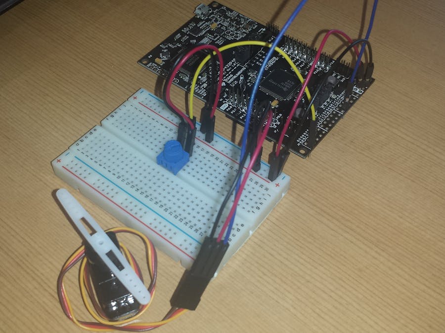
Servo Control with Potentiometer
Hardware Required:
· Texas Instruments Launchpad
· Potentiometer
· Servo
· Breadboard
· 8 Jumper wires
What is a potentiometer and how does it work?
- A potentiometer is an adjustable resistor which consists of a wiper that slides across a resistive strip to deliver an increase or decrease in resistance. The level of resistance will determine output of current to the circuit. With this device we will be able to control the direction that the servo will move by turning the potentiometer either clockwise or counterclockwise.
What is a Servo?
- This is a device that converts an electrical signal and translated that into
moving an output shaft. This shaft can be positioned to specific angular
positions by sending the servo a coded signal (which we will utilize the pot
for)
What is Digital Write?
Computers are digital devices, meaning they perform all calculations using ones and zeroes. This method of computing is referred to as the "binary system," and is the heart of all digital technology. Devices such as hard drives, CD recorders, and Mini DV camcorders are digital devices, and therefore record data digitally, as ones and zeroes. This only allows the output to be set as either HIGH or LOW. Although it may seem very simple in that something is either on or off at a particular moment, it is still possible to create an illusion for something to seem halfway on. For example, an LED may be completely on or completely off, but if it turned on and off very rapidly, it would create the illusion that makes the LED look dimly lit. This is one method for making an output something different from completely on or off.What is Analog Write and Pulse Width Modulation?
Another method for adjusting the intensity of an output is to use analog write, also known as PWM (pulse width modulation). After a call to analogWrite(), the pin will generate a steady square wave of the specified duty cycle. Analog write is a much simpler method to adjust intensity because it allows the user to select a single value from a series. For example, setting an analog write value as 100 for an LED will make the light turn almost halfway on because LEDs range from 0 to 255, where 0 is completely off and 255 is completely on. Therefore, the LED has 255 steps of intensity. This range of numbers may be different for other devices, but the general function is the same.
Fritzing Diagram:
Opening Energia:
-For this tutorial we will be using the coding software Energia. Go to energia.nu and download the software for your computer. After installing Energia, then click: FILE > EXAMPLES > SERVO > KNOBConstructing the Circuit:
It is advised that when you making the circuit, it should be as similar as possible to the Fritzing Diagram above. If you have a different Launchpad, you should know that the middle wire that comes from the potentiometer will be inserted into any Launchpad pin that allows “Analog Read”. Similarly, the extra wire from the servo that is neither ground nor power needs to plug into any Launchpad pin that allows “Digital Write”. Both of these are important to follow because the input from the potentiometer will be an analog input that needs to be read by the Launchpad. To control the Servo, you need a Digital Write pin, so the input from the Pot will be translated (or written) onto the Servo.CODING:
Following the two tips in the previous paragraph, the next step is to substitute those pin #s into the coding so Energia can input and output data. After opening up the “Knob” tutorial, you will see the lines of coding that say:Like it describes in the green font, this is the spot where you put the Analog pin which you used to connect the potentiometer to the Launchpad. Change “PE_4” into the pin number. If mimicking the or the Fritzing diagram, would type in “2” in that place.
Similarly, this line of coding is there you will substitute "PF_1" for the pin that you have connected the servo line too. If mimicking the Fritzing diagram exactly with that Launchpad then you will change the "PE_1" to "14". For all other Launchpads, you must locate the pin diagram to correctly find the pin # that will be inserted into the coding.
Press Compile and Upload your manipulated coding onto the Launchpad. You are now able to control the servo just by twisting your potentiometer!
Troubleshooting:
· Check for errors in Energia debug window. The compiler will tell you what is happening. Errors are in red text.
· Sometimes your LaunchPad gets stuck or hung up on the previous code. Unplug your LaunchPad and plug it back in to perform a full reset. This is called a power on reset. Sometimes using the RESET button can work but taking away the power and letting the microcontroller fully reset is often best.
· If you have a failure to upload it could be your drivers are not properly installed. Energia will sometimes give the error “No unused FET Found” which means it can’t find a LaunchPad connected to your computer. Make sure you download the drivers for your operating system found on the Getting Started Guide.
· Make sure your pins are correctly connected. Use the diagram above to assist you.


Comments
Please log in or sign up to comment.