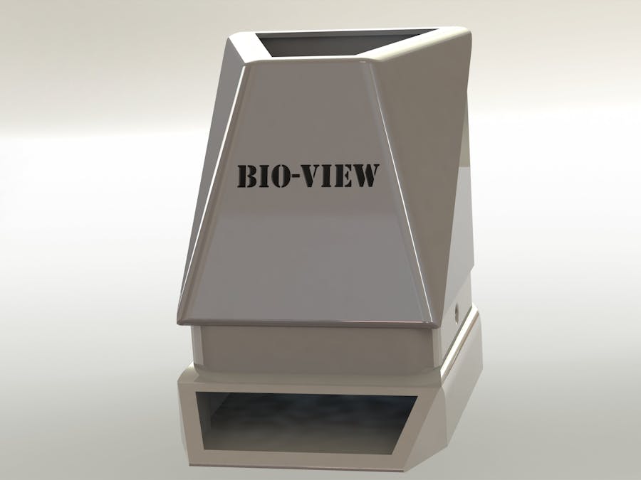
Real-time imaging of live cells under physiological conditions (5%CO2 atmosphere under 37 degrees celsius) provides valuable insight towards better understanding of stem cell development, behavior, and differentiation over time. However, live cellular cell systems often are big, expensive, and only offer singular cell culture incorporation at one time.
Initially we had an idea to make a multichambered bioreactor to test different culture medium conditions flowing through each chamber but decided to incorporate more electronics to make a real time imaging device and to just use different medium conditions/cell types in each chamber(dish holder).
Instead, we decided to prototype a multi-chambered live imaging system that would allow multiple cell cultures to be observed at the same time, whilst either controlling oxygen levels to study effects of normoxia vs hypoxia or to maintain physiological CO2 levels. We decided to name our project Bio-View and plan on incorporating a humidity/temperature sensor, an overhead Raspberry V2 camera which could be moved vertically via a platform system as well as infrared LEDs in an interdisciplinary effort to improve this device.
UW-MakeathonDay1:
After the opening speeches and dinner, the UW-Makeathon was off to a start! After team formation, we started on the design of the device, starting from what problems it would help solve, what features could be incorporated and how we would breakdown our initial tasks. Jerry and Kevin worked initially on the CAD design of the parts that would make up the body of the Bio-View device while Matt worked on initializing the software/hardware system.
Software/HardwareMatt worked on initializing the Raspberry Pi system and connecting and working with Arduino units which would be used to collect data from the temperature sensor units as well as controlling gas flow through system, a potential CO2 sensor(Or O2 sensor if we cannot find one), as well as a heating unit. The Raspberry Pi OS was successfully initialized and Matt began working on the controllers and software to control the sensor units. We planned on calibrating the temperature sensor unit using boiling water followed by freezing cold water as per online instructions and moved this task to the second day. The temperature sensor was successfully hooked up to the Arduino, giving data measurements back to the main Raspberry Pi and the display monitor was able to display this feedback.
CAD/3D-PrintingFor the device, we first designed a middle insert which had 4 circular chamber cutouts with diameters of 6 cm to hold standard 60mm cell culture plates. This could be adjusted for different sized cell culture plates and this had an advantage over 6 well plates in that we could minimize cross contamination of samples if we were working with different cell cultures. A grooved top cutout would be used to lock a lid in place. Two circular holes were made on the front and back walls for gas to flow in and out of. We planned on 3D printing adapters for this portion to connect to piping. We then designed a lower layer which would hold the middle insert as well as provide room for some of the hardware and sensors to go in as well as room for a small display for temperature, gas concentration. A lid was planned to be formed of acrylic to easily observe the cells from an upper view and inserts that would fit the grooved portions of the middle insert could be easily glued to this lid. An upper box lid to house a Raspberry Pi V2 camera was designed as well as a motor controlled mechanism to adjust camera height for focusing.
UW-MakeathonDay2:
After spending the night working, we tried to take a brief nap in the morning. We arrived at the Makerspace to start the 3D printing of our lower tray to hold the middle insert in. This was broken up into two pieces to reduce time. I used Adobe Illustrator to make a template to laser cut two 16x16x1/8" acrylic sheets for the upper lid and bottom of the middle insert so that the cells can be observed and imaged. We started the 3D printing of our top portion which would house the camera as well as platform system and the locking grooves to attach on to the lids. Today, we finished 3D printing the components to stabilize the camera platform Two trapezoidal acrylic units were laser cut to form the top unit and a adapter was 3D printed to attach the motor onto the platform.We managed to gain valuable insight in prototype engineering from X and X and had an idea to partially try to waterproof/gasproof our middle insert section through wiping the 3D printed PLA with acetone, or to use thermofolding to present a water sealed layer on the outside.
On the software side, we managed to get the heading pad working which could be attached to the bottom of our middle insert to replicate physiological temperatures. We also obtained a humidity/temperature sensor which was successfully incorporated and presented humidity and temperature feedback.
UWMakeathonDay3:
We finished putting together the hardware in the 3D printed base of our device with a strip connecting to the upper layer for the camera. We 3D printed another middle insert and integrated velcro strips to hold up the heating pads which could be removed and replaced if imaging was to be performed on a inverted light microscope. Infrared LED strips were placed on the sides of the middle insert so that infrared images could be picked up and viewed on a web browser.


_ztBMuBhMHo.jpg?auto=compress%2Cformat&w=48&h=48&fit=fill&bg=ffffff)


Comments
Please log in or sign up to comment.