Portable lighting station synchronized with music.
Always use technology to improve the world, if you are a black hat or gray hat hacker please abstain at this point......... or at least leave your respects to make me feel less guilty XP.
IntroductionNowadays for an organizer or independent musician, events, reunions and parties may not follow the traditional way of arriving, playing and leaving. Fans today require a higher level of entertainment, which led to organizers having to buy expensive lighting and sound control systems to achieve the level needed for the fans' show.
This type of lighting systems have a complex and expensive system of controls to handle each of the lights, most of the time it is necessary to set up a light show beforehand for each of the songs, increasing even more the costs.
Here are some similar products in the market, which are of very low quality:
- MICTUNING 2nd-Gen RGB LED: https://www.amazon.com/dp/B01FWXT11I/ref=cm_sw_r_tw_dp_U_x_-DvoCbVYSEJ9S
- LED Strip Lights with Music Sync-Chase: https://www.amazon.com/dp/B07HCH24GL/ref=cm_sw_em_r_mt_dp_U_NCvoCb1G7DEZZ
None of the products available in the market sell for less than 40 dollars. They only allows the control of low power elements such as LED's, but if we really want to control high power elements we need a circuit that is capable of it without risking the controller, in this case an Arduino.
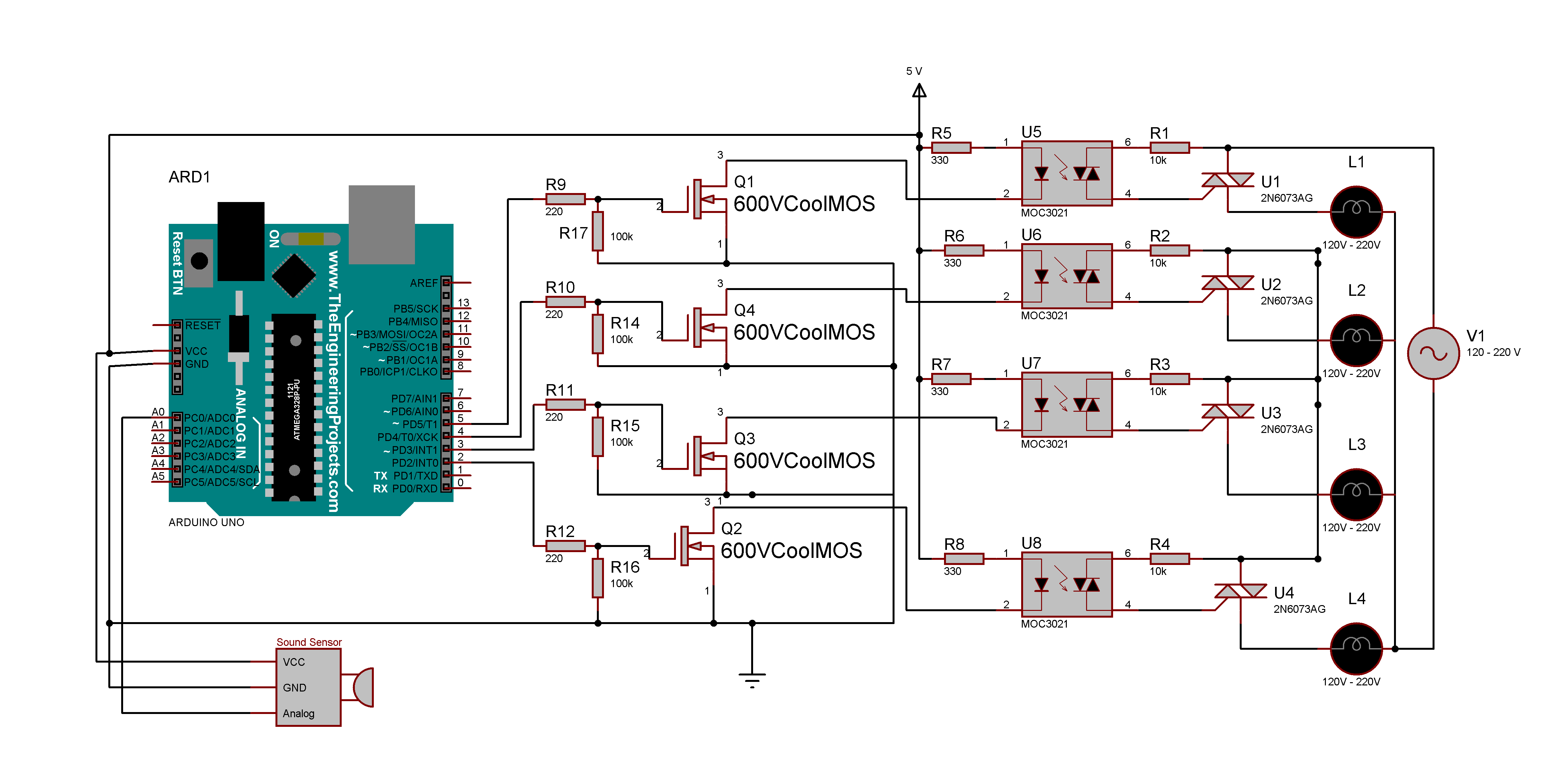
The purpose of the circuit is to switch from a digital signal of 0-5 V DC to a control signal of 120 V AC.
In the first stage of the circuit we have an Infineon 600VCoolMOS C7 MOSFET, which will allow us to control the optocoupler demanding the minimum current to the Arduino board, because the optocoupler requires at least 5 volts at 36mA to be able to drive. This is very close to the limit of the current that the Arduino board can supply, however the 600VCoolMOS only requires a signal of 5 volts at 60uA, thus showing an excessive improvement in the consumption that it requires from the board.
This consumption is extremely important because it gives us the possibility of being able to literally use any controller to perform this task due to its low consumption, thus not requiring more expensive drivers that can supply said power in their ports.
The MOSFET's operation is to ground the optocoupler diode, once this is activated it allows the flow of energy through the DIAC and this in turn allows the passage of current in the TRIAC connected to the lamp and igniting it in the process.
The other great advantage of using the MOSFET is the ease of increasing the number of drivers as in Image 1 or using more powerful drivers as in Image 2 without changing the design of the main circuit.
Different results in different boards:
Another solution to this project would have been to use relays, which have the function of performing this same task but mechanically, by generating a "Click" on each switch. The problem with this type of component is that if we use dimerizable lights or the switching frequency was larger, the relay could not perform this task, which the mosfet, optocoupler and triac can easily do.
For this project it is possible to make individual modules to be able to expand the number of bulbs or high voltage devices connected to the Arduino or to any other board.
You can also make a complete module for 4 AC outputs this in order to integrate the entire system on one PCB, both files are in the "PBC Files" folder in the Github or in the footer of the project.
To develop this circuit, we first tested each of the stages were carried out to demonstrate its effectiveness, the first circuit to be tested was the control of the bulbs by means of a button and safety gloves due to high voltage. (Please if you are to replicate the experiment use any safety measures possible, playing with live current is not wise).
For the second circuit since the Lamp control works well, a platform with LEDs was made to see how the Arduino controlled the lights to the rhythm of the music, the code is in the "Arduino Code" folder, the code is thoroughly commented.
Once we saw that the lights control worked, we connected all the components of the whole circuit in a protoboard, to control the 4 lights and connected it to the Arduino.
As you can see this was done in steps to manage safety, I repeat it is dangerous managing live 120V AC power so take any precautions into consideration.
The Final ProductWith the circuit running, we decided to make control modules like the one shown in the image to not depend on any cable failing in the breadboard.
The board was made based on the one that is in the folder "PCB Files" however since we did not have transfer paper we had to make the vias with a sharpie. It is a permanenr marker so when you dip the plate in ferric chloride it survives, this process is the classic one for making homemade PCBs. You can get to know more about this process in the following link:
https://www.hackster.io/Junezriyaz/how-to-make-pcb-using-marker-531087
After making three aditional PCB's, we decided to put the entire circuit in a box, covering it and with 4 identical lamps so that this was a more aesthetic product and easy to transport.
And we are done! With this we have finished the light synchronization system for electrical elements (120 or 220 volts).
Comments:This project was carried out in order to demonstrate that the control of lights through microcontrollers can be efficient and cheap, since current systems at a much lower quality are sold at excessive prices and therefore not available to all.
And to showcase a creative and seldom seen approach to use the CoolMOS C7 MOSFETs provided by Infineon
ReferencesAll the information about the technology used, and direct references are in our wiki:


_ztBMuBhMHo.jpg?auto=compress%2Cformat&w=48&h=48&fit=fill&bg=ffffff)


_3u05Tpwasz.png?auto=compress%2Cformat&w=40&h=40&fit=fillmax&bg=fff&dpr=2)
Comments
Please log in or sign up to comment.