In many areas of automation, the great need is to carry out the processes automatically and without human intervention.
And several processes of industrial and residential automation, work based on one variable: the time. That is, the operator parameterizes the equipment to perform a certain process at a specific time and, when the clock is at that time, the system starts executing an activity.
In this project, you'll learn step by step how to develop this system in partnership with the PCBWay Factory.
The ProjectFor this project, we will develop a system with human-machine interface presented in a 16x2 LCD, so that the user can communicate with the system and enter the information necessary to trigger the load at specific times.
In this way, I will present to you the model of how the system will be built and its functionalities.
Based on Figure 1, the Arduino UNO will be programmed to process information for the entire project. And among the components used, which will be connected to the Arduino board, we have:
And each equipment will have its proper functionality in this project.
- The buttons will be used to set the desired time for the load to be triggered;
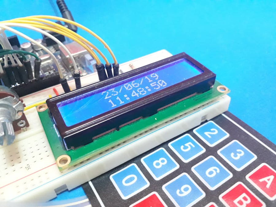
- The LCD will be used to transmit the timer information to the user and display the parameters entered by the user in the system;
- The real-time clock will be used to count the time in hours and exchange this information with the Arduino UNO;
- The relay will be used to receive an Arduino command and trigger the load, which in our case will use a light bulb.
In the next few articles, you'll understand the step-by-step process on how to develop all the electronic design and programming for your device to trigger loads based on the user's pre-set time.
Flowchart of the Process of Programming the Timer ClockBased on the project construction process, it is important then to model the entire flowchart, to facilitate the implementation of the code for system programming.
In Figure 2, I present the modeling project, to facilitate the understanding of each step and the actions that will occur during the execution of the code.
The project is simple. After starting the initial loop, the condition checks whether it is the first time the machine is being started or if it occur a reset by the user, so the date and time must be set.
If yes, the system will prompt you to update the new date and time and then prompt you to set the actual time and the time at which the load should remain on.
After setup, the system will display the updated time and date on the 16 x 2 LCD display.
In this system, two functionalities were implemented:
- Update the date and time of the system;
- Reset all date, time and time information and triggering of the load.
In the first decision after the command "Show Time", is verified. And, if the condition (check if adjust time button is pressed) is true, the adjust time function will be call for the user configure the date and hour correctly.
In the second condition (check if reset time button is pressed), we will check if the reset button has been pressed. If this is true, the function will be called and the date, time and hour of trigger the load will be cleared and a new date, time and hour of trigger the load will be set.
After this, there are two more conditions to check if the time is equal to the time chosen to trigger the load. If this is true, the load will be triggered (third condition).
And it will only be disabled when the time is equal to the time programmed by the user (fourth condition).
After this, the code return for the beginning of the loop.
Now, if you are interested in following this series of articles in partnership with PCBWay, follow us and learn how to develop this project step by step.
AcknowledgementsThank you for reading our article and, if you like, click on enjoy the article, to help us and follow our profile here at Hackster.
We appreciate the support and partnership of PCBWay in the production of electronic circuit boards, by encouraging and improving the quality of our projects.
The Silícios Lab thanks UTSOURCE to offer the electronic components.


Comments
Please log in or sign up to comment.