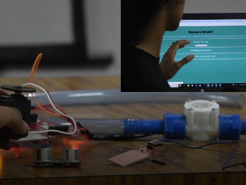
The source idea of this project is Smart Water Management using Smart Taps.
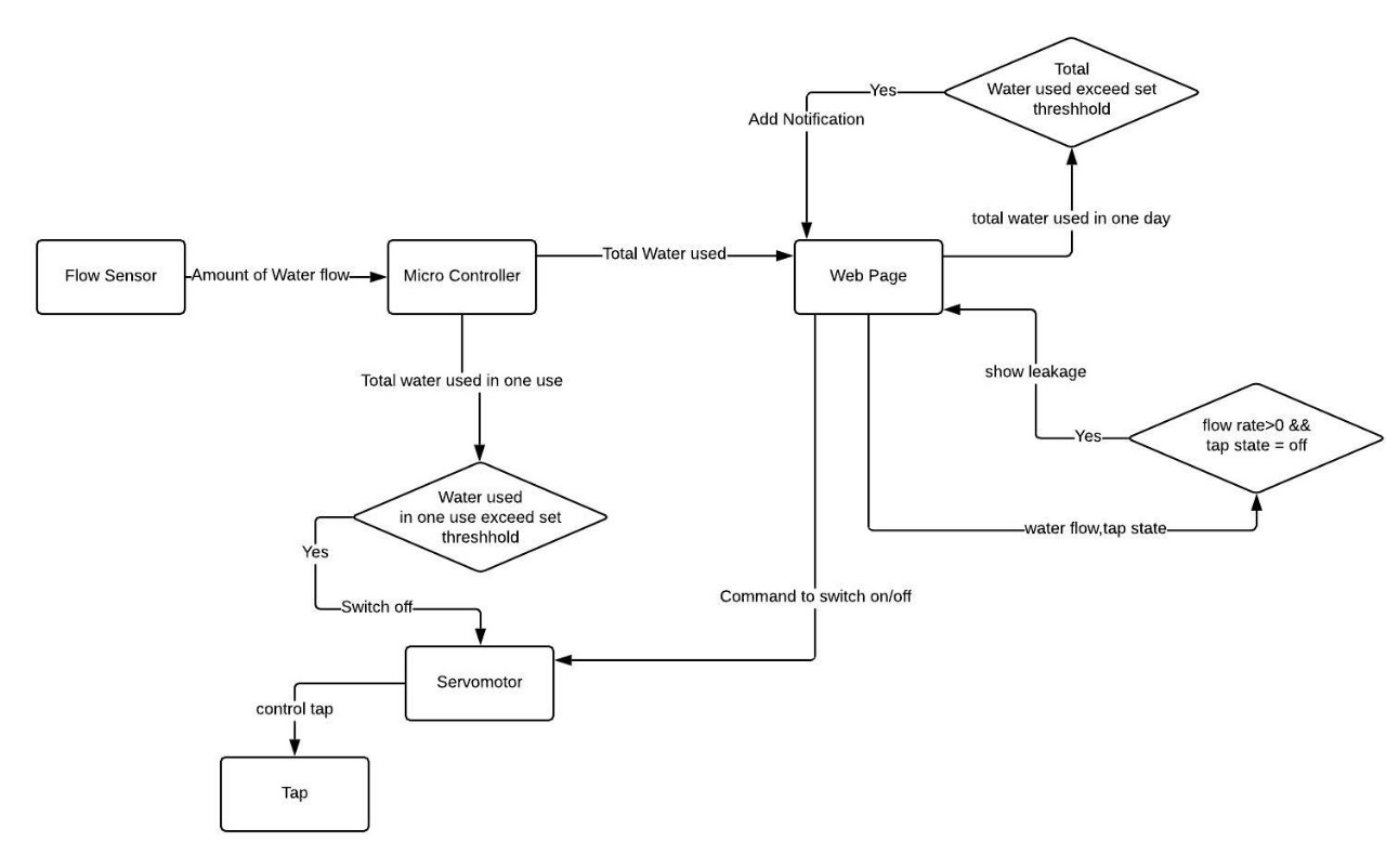
By automating taps, we can measure the amount of water being used by an individual. This amount is displayed on a website. If the water being used exceeds a given threshold, a notice is put up on the website displaying that there is excessive usage.
The user can remotely switch the tap on or off using the website. Taps are attached to the servo motor, which is controlled via the online website. Furthermore, If it exceeds another specified quota, then the tap is automatically shut.
If the tap is switched off and flow is detected by the flow sensor, the user is notified of the presence of a leakage in the tap through the tap. Flow sensor calculates the rate at which water is flowing through the pipe, and the amount of water flown through the tap. It acts on the principle of a hall effect sensor.
Why?This idea can be scaled to the taps placed in hostels as students on campus are quite ignorant about the amount of water they use everyday. Notifying them of their usage could go a long way in preventing wastage.
- A leaking faucet can waste 4,000 drops of water, which is equal to a litre of water.
- On an average one person wastes about 0-45 litres water per day. To understand it better, it is 30% of water requirement per person per day.
A number of IoT Smart water management systems were tailored for major cities, or houses, but there doesn’t exist a system that is tailored for hostels (which have a large number of users) and this system is created to be user friendly.
Step 1
Make the connections. Connect the data pin of the servo to pin 3 on the launchpad, and connect the data pin of the flow sensor to pin 4
Step 2
Upload the sketch onto the launchpad, after editing the SSID and password for WiFi connectivity.
Step 3
Open the serial monitor and copy the IP address onto your web browser.
Step 4
Pour water through the flow sensor, and refresh the page to see if the value for amount of water used changes. Click on switch off and switch on buttons to move the servo.
Further Comments about hardware usedCC3220
The applications MCU subsystem contains an industry-standard ARM Cortex-M4 core running at 80 MHz. SPI flash for Wi-Fi network processor service packs, Wi-Fi certificates, and credentials.
With on-chip Wi-Fi, Internet, and robust security protocols, no prior Wi-Fi experience is required for faster development. The CC3220MOD integrates all required system-level hardware components including clocks, SPI flash, RF switch, and passives into an LGA package for easy assembly and low-cost PCB design. The CC3220MOD is provided as a complete platform solution including software, sample applications, tools, user and programming guides, reference designs
The CC3220 Sketch (code) uses the external interrupt (int 0) on CC3200 pin (P03). This is used to read the output pulses coming from the water flow sensor. When CC3220 detects the pulse, it immediately triggers the pulseCounter() function. This function then counts the total number of pulses detected ( interrupts).
Flow Sensor
Effective water management involves supplying water according to the real requirement, and thus measuring water is very essential step in water management systems. There are many water flow measurement techniques as well as different types of water flow meters used to measure the volume of water flow in pipelines but these all are too costly. This article describes ideas for design and development of low cost automatic water flow meters, with the help of readily-available and low-cost water flow sensors.
Hall-Effect Water Flow Sensor
Accurate flow measurement is an essential step both in the terms of qualitative and economic points of view. Flow meters have proven excellent devices for measuring water flow, and now it is very easy to build a water management system using the renowned water flow sensor YF-S201. This sensor sits in line with the water line and contains a pinwheel sensor to measure how much water has moved through it. There is an integrated magnetic Hall-Effect sensor that outputs an electrical pulse with every revolution. The “YFS201 Hall Effect Water Flow Sensor” comes with three wires: Red/VCC (5-24V DC Input), Black/GND (0V) and Yellow/OUT (Pulse Output). By counting the pulses
from the output of the sensor, we can easily calculate the water flow rate (in litre/hour – L/hr) using a suitable conversion formula.
Flow rate can be determined inferentially by different techniques like change in velocity or kinetic energy. Here we have determined flow rate by change in velocity of water. Velocity depends on the pressure that forces the through pipelines. As the pipe’s cross-sectional area is known and remains constant, the average velocity is an indication of the flow rate. The basis relationship for determining the liquid’s flow rate in such cases is Q=VxA, where Q is flow rate/total flow of water through the pipe, V is average velocity of the flow and A is the cross-sectional area of the pipe (viscosity, density and the friction of the liquid in contact with the pipe also influence the flow rate of water).
• Pulse frequency (Hz) = 4.5Q, Q is flow rate in Litres/minute
• Flow Rate (Litres/hour) = (Pulse frequency x 60 min) / 4.5Q
In other words:
• Sensor Frequency (Hz) = 4.5* Q (Liters/min)
• Litres = Q * time elapsed (seconds) / 60 (seconds/minute)
• Litres = (Frequency (Pulses/second) / 4.5) * time elapsed (seconds) / 60
• Litres = Pulses / (4.5 * 60)
Connecting the water flow sensor to CC3220 requires minimal interconnection. Connect the VCC (Red) and GND (Black) wires of the water flow Sensor to the 5v and Gnd of CC3220, and link Pulse Output (Yellow) wire of the water flow sensor to CC3220 pin P03. Note that the water flow sensor is not a power-hungry type; it draws a maximum of 15-20mA at 5V DC input!
Servo Motor
Futaba S3003 - Servo Standard
Specifications
Modulation:Analog
Torque: 4.8V: 44.00 oz-in (3.17 kg-cm); 6.0V: 57.00 oz-in (4.10 kg-cm)
Speed: 4.8V: 0.23 sec/60° ; 6.0V: 0.19 sec/60°
Dimensions:Length:1.57 in (39.9 mm)
Width:0.79 in (20.1 mm)
Height:1.42 in (36.1 mm)
Gear Type:Plastic
Rotation/Support:Bushing
Rotational Range:60°
Pulse Cycle:30 ms
Pulse Width:500-3000 µs
Connector Type:J
Because servo motors use feedback to determine the position of the shaft, you can control that position very precisely. As a result, servo motors are used to control the position of objects, rotate objects, move legs, arms or hands of robots, move sensors etc. with high precision. Servo motors are small in size, and because they have built-in circuitry to control their movement, they can be connected directly to an CC3220.
Most servo motors have the following connections:
• Black/Brown ground wire.
• Red power wire (around 5V).
• Yellow or White PWM wire.
In this experiment, we will connect the power and ground pins directly to the CC3220 5V and GND pins. The PWM input will be connected to one of the CC3220 digital output pins.


Comments
Please log in or sign up to comment.