Team members
Bohan Jiang
Li Fang
Yifu Liu
Affiliations
University of Michigan Dearborn
KPIT
Emails
Bohan Jiang(bohanj@umich.edu)
Li Fang(lifa@umich.edu)
Yifu Liu(yiful@umich.edu)
Problem statement (Project Background)
In current life, as people are becoming busier and busier, they are also becoming more easily forgetful, they would fail to take of the details to improve quality. Take students as an example, when they hurry to class, they could not open the window because they are not sure if it will rain later. And they may also leave the stove on because they were interrupted by something else when about to switch off the stove. Such small details could result in influence of different levels. And the system we are going to introduce here, is to prevent such influence from happening.
Goals (General Idea of Project)In general, our system consists of three subsystems, stove switch monitor, door lock monitor and air circulation system.
The stove monitor is going to check the switch status and once if the switch is on, the system will turn off the power supply in case of overheating issue happening. Also, we offer an online function here to help the users control the power supply more conveniently, by visiting the controller through network browser.
For the door lock system, it will check if the last user has closed the door and/or turned the lock. Alarm will work if neither of these two status fails to meet the standard, as the door would be meaningless if you forget to close or lock it.
The air circulation system here would gather the outdoor air factors (oxygen percentage, humidity percentage) , when the system "think" the condition is good (we do manually setup as standards currently), it will open the window for a fixed time (or closed if the outdoor air quality suddenly changed).
Approach (How the Systems Work)1. Stove Monitor System
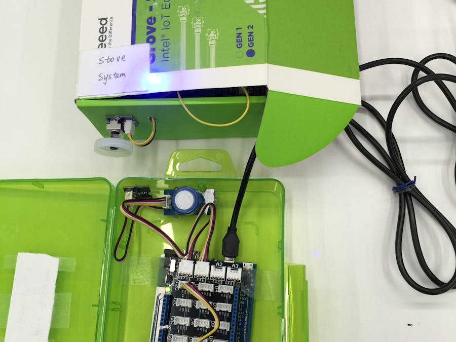
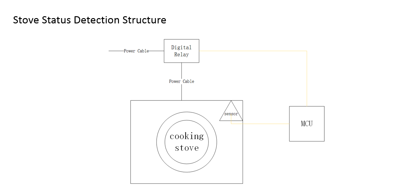
In this system, we introduced angular sensor and digital relay as key parts. Also, Intel Edison worked as MCU for the whole system.
The angular sensor will be installed beside the rotatory switch. By install gears on both angular sensor and rotatory switch, when we rotate the switch, the angular sensor will also work at the same time. In this way, we can read the rotation of the switch (by using the value of the angular sensor) in real time. What's more, the only the results we want to know would be "on" and "off". So if the value we get from the sensor is not within the specified range, we would treat the switch as on, and then it comes the digital relay. Another benefit to use the gear set is that the rotation range of the angular is strictly limited, while the range of the switch can meet almost 340 degrees, to meet such a difference, we can choose special gear set with different teeth ratio, in case the system cannot work normally.
To control high voltage with low voltage is a popular use of digital relay, so here we use it to control the power supply of the stove. When value we get from the angular sensor does not satisfy the requirement, it means the stove is on, and then MCU is going to turn off the relay to "cut" the stove power system.
In this way, we do prevent the stove from heating when no person is at home.
One more thing we want to mention here is our original design about the stove system. We planned to use temperature sensor at first, instead of angular sensor. But there would be some problems to conquer when we decided to monitor the temperature. The first thing would be how to judge if the stove is closed with the changing temp curve. The second issue is the durability of the sensor, so what could happen when the sensor is exposed to high temperature. The third issue is the accuracy of the sensor. As the stove is at low-temp level, could the sensor detect the temp, especially in winter? According to these consideration, we gave up the design of temperature sensor.
2. Door Lock System
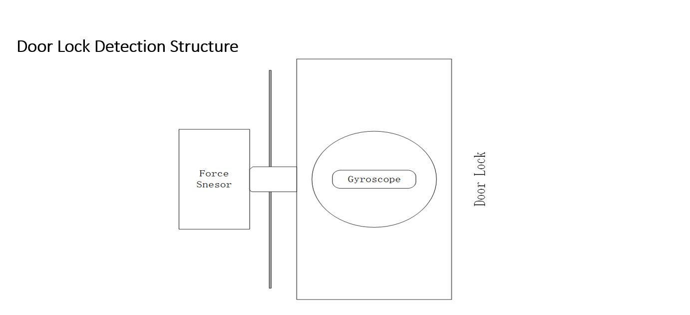
In the door lock monitoring system, we also use the angular sensor as a part of this subsystem. One more sensor we are using here is the button sensor.
As we know that the button can generate only high and low voltage levels, which stand for 1 and 0 in logic. The system would receive high level only when the button is pressed, which means the door is closed in our test environment. Once the door is open, there will be no pressure on the button, and the system will receive low level as a result. The button sensor will set up in the strike case so that it get close touch with the latch bolt to test the pressure.
The position of the angular sensor will be similar to the one in the stove monitoring system, it will sit beside the cylinder, and with gears attached to them both, the angular sensor can detect the angle of the cylinder accurately.
Also, as a potential bonus, once we introduce motor into this system, it would be possible in theory to control the status of the lock. And this would be enough when you get handful things, you just need a click before you get off your car.
Our original design about this part is to use the gyroscope to detect the cylinder’s position. But it turned out to be the gyro would not be best solution as the scale of the sensor could be first problem that we have to go through.
3. Air Circulation System
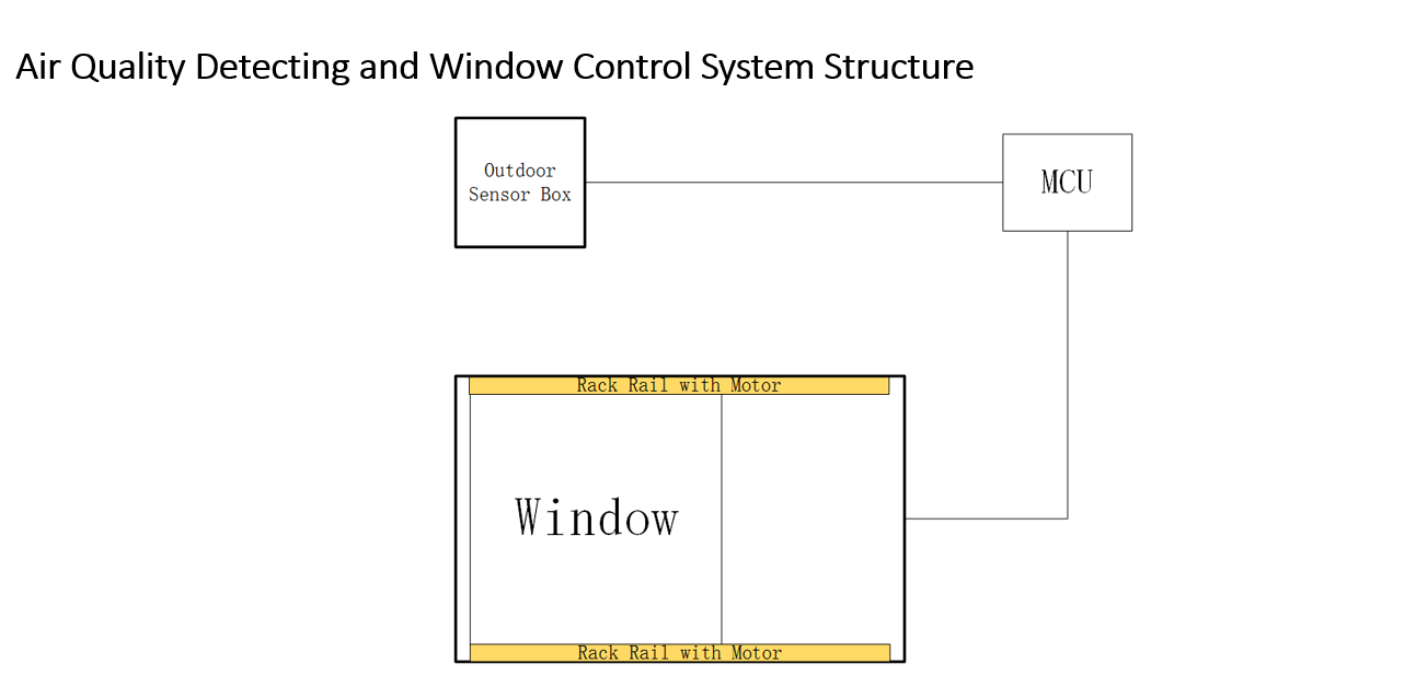
Generally, our air circulation system consists of two parts, sensor box and window control unit. For the sensor box, it include oxygen sensor and temperature, and we are going to add humidity sensor into the box once the code work is done. For the control unit, we use motor drive board and a DC motor to control the window, with gear rack rail set for sliding.
We will put the sensor box outdoor to detect the oxygen percentage and temperature. Also, we will look into local weather report and conclude with data which stand for good air quality. Then we will input the data into the system manually as the threshold for sensors. One the values we got from the sensor meet the thresholds, the MCU will operate the motor via driver board.
When the time gap meets the fixed time (or when the outdoor factors change, as we will do the check periodically while the window is open), the MCU will operate the motor to close the window.
At first we plan to use two sensor boxes to do a comparison, but in consideration of save the expense, as the oxygen sensor is a little expensive, we gave this idea up finally. One more thing we can do to make this system better, we may introduce data mining into our system, and in this way, all the thresholds will be up to date daily or even hourly. We believe that Intel Edison is powerful enough to handle such data processing.
For air circulation system, we used one box to detect the outdoor air quality, which could be much easier. For window control part, our use rail rack with gear and motor together as a small operator system.
In the whole project, the mechanical part (gears, rail racks) will not show up as demo. But we will offer detailed introduction of these parts. Gear teeth ratio is a hard question in this part.
Design & Implementation
System block diagram
Here is the link for the demo video on YouTube:
https://www.youtube.com/playlist?list=PLVmm4GbSFRNdnwM9wtief4qWqZET4ZwCg
The gear set we mentioned in our combo, but as they are not compatible with our devices, still we cannot include in our system:
The systems work well in both offline mode or in local access network. We will offer video demo for more details.
LessonsWhen we introduced the gears into our system, we do solve many problems. But meanwhile, they offer us better platform with much more possibility. We have connected our systems into local network, it means that we can also send commands to our system while we are reading information from the systems through web browser. So what if we add an extra gear attached with a motor in each gear combination? We can image that once when we control the motors, we are rotating the gears, which means we are controlling those monitored switches in reverse way. This could be a good direction for the system development.


_wzec989qrF.jpg?auto=compress%2Cformat&w=48&h=48&fit=fill&bg=ffffff)


Comments