The RoboARM utilizes a TM4C123GH6PM microcontroller to interpret inputs from an old analog joystick to control the servos that drive the arm; while at the same time making sure that the arm abides by the set movement bounds of the hardware. The microcontroller implements the added functionality of being able to record, store, and ultimately repeat routines that the operator performs.
The robotic arm was designed and built in five different phases.
- Phase 1: 3D-printing the Robotic Arm and Claw
- Phase 2: Reverse Engineering the Joystick
- Phase 3: Ports selection and μController wiring
- Phase 4: Programming the TI TM4C123GH6PM μController
- Phase 5: Testing and Adjusting Functionality
During phase 1, the structure of the robotic arm was 3D-printed using the TEVO Tarantula 3D-printer. For the purpose of this project the arm was printed using PLA as it is a cheap and reliable 3D-printing material. The arm was found on the popular website thingiverse.com which is an open source website where people share free 3D model objects. Figure 1, shows the 3D-printed structure of the arm.
Furthermore, the claw was 3D-printed in the same manner and the model was also found on thingiverse.com. Figure 2 shows the 3D-printed claw.
After printing both the arm and the claw the four MG995 servos were installed as shown in Figures 3 and 4.
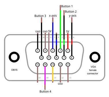
The first goal of phase 2 was to determine how the joystick works internally in order to be able to utilize its outputs in a predictable manner. This involves powering the joystick while manipulating its controls in order to document the functionality. The pinout of the joystick was determined to be as shown in Figure 5.
This is where the first challenge was encountered. The joystick works best at 5V and thereforeoutputs at 5V logic for both the digital buttons and analog joysticks. However, the TM4C123GH6PM microcontroller’s digital inputs and ADCs function at 3.3V logic levels as shown in Figure 6. Therefore, it was called-for to design circuitry that maps the 0V-5V outputs from the joystick into the 0-3.3V range. These calculations are shown in Equations 1 - 4 below, with the resulting circuits being shown in Figures 7 & 8. The first implementation of this circuit was then created on a breadboard for testing and tuning purposes as shown in Figure 9.
After wiring the circuit, a small testing program was written to confirm that all the buttons and axes were working properly as shown in Figure 10.
Next, after verifying the proper functionality of the buttons and axes based on the resistors chosen, the circuit was designed on a prototyping board as shown in Figure 11.
With the schematic shown in Figure 11 the circuit for the joystick was built and connected to the VGA connector as shown in Figures 12 and 13.
During phase 3, the ports on the microcontroller were chosen based on the functions that those ports support. Figure 14 shows the pinout of the TM4C123G microcontroller labeling which pins are analog and digital.
Based on the pinouts in Figure 14, the ports used for the joystick and arm are listed in Table 1 and Table 2.
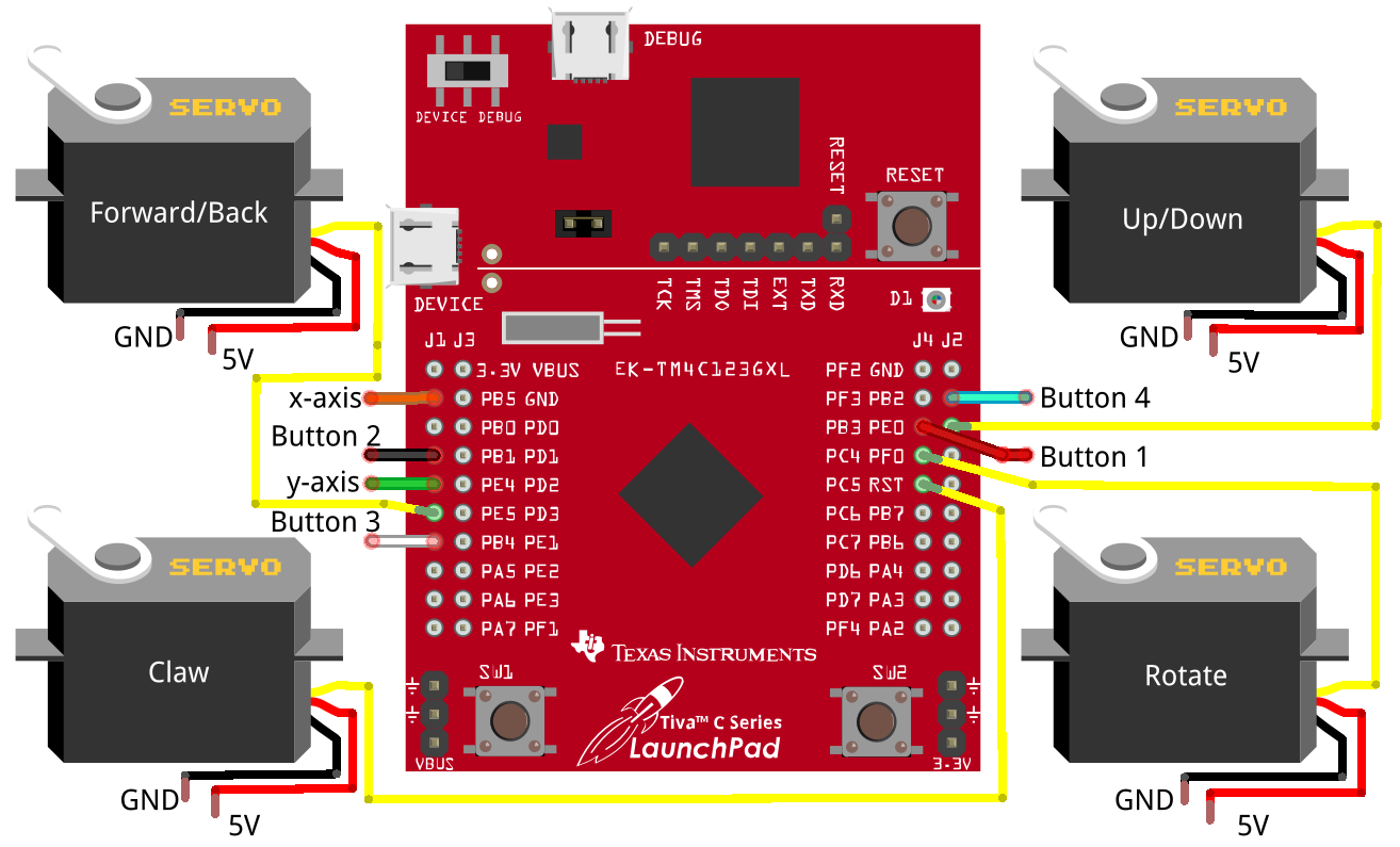
After defining the ports for the arm and joystick, the wires were connected to the microcontroller as shown in Figure 15.
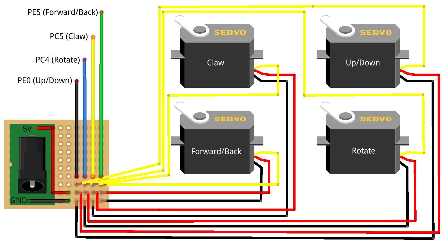
Figure 16 displays how the control signals and power are delivered to the servos. A barrel jack is soldered to a piece of protoboard with the power from the hack bridged. The control signals from the Tiva C are then routed to the data pins of each respective servo.
Figure 17 shows the wiring of the servos as well as how each controller is powered up. It is important to know that the microcontroller is connected directly to the usb port to the computer. The servos are powered up by the 5V 3A power supply and the Joystick connector is powered up by the 5V 1A power supply.
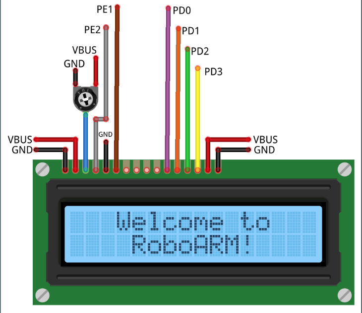
Furthermore, the ports for the LCD display were also chosen based on functionality. Table 3 shows the ports chosen on the microcontroller for each Pin of the LCD Display.
Finally, the LCD was also connected to the microcontroller with its circuit setup as shown in Figure 18 and 19.
Joystick Calibration:
After the circuitry for the joystick was created and tested to work properly, programs were created to aid in the software calibration process. The first goal was to adjust the trim such that there was equal resolution on both sides of each axis. In order to accomplish this goal, the x_delta_low_mid, x_delta_high_mid, y_delta_low_mid, and y_delta_high_mid outputs were created. To use these, a starting point was established upon start and the joystick was moved to the max position in each direction. The corresponding variable would indicate the maximum change in that direction from the starting point. The trim linear potentiometers were then used to calibrate the axes such that they had approximately the same total change in each direction; ie the starting point was in the center of the range and not biased to one side.
The next goal was to account for the high sensitivity of the analog joystick inputs. Because the ADCs are 12 bit, naturally there is more resolution than required for the desired behavior. This caused the arm to constantly twitch and move upon initial testing. The delta variables confirm that even when not touched, the joystick axes values fluctuate significantly without user input. It was then decided that to address this issue, a deadzone would be needed so that inputs within a specified range of the starting point would be ignored and the arm would only move if the joystick was moved outside of this range. A deadzone requires a starting point and threshold on either side. To determine the starting point, variables X_avg and Y_avg were created that keep track of a rolling average of the starting position. After letting this program run for a minute or two we were confident with our starting positions. The delta variables were then monitored to determine the natural fluctuation of the values. With some trial and error, values were decided upon that eliminated accidental movement. The output of this program is shown in Figure 20.
Movement Bounds Calibration:
The next goal was to ensure that the servos would not move the arm past its physical limits allowed by the structure. In order to accomplish this, a DEBUG preprocessor directive was created. When this variable is defined and the program recompiled, the microcontroller will print to the serial monitor the position of each servo along with other debugging information. This is only enabled when needed because repeated “Serial.print” calls drastically reduce performance. Each axis was carefully moved to the maximum in each direction that the physical structure would allow. These values were then recorded and defined in the program as constants that could easily be changed and adjusted later. Throughout the program, the movement bounds-checking refers to these constants so that their values only need to be changed once. This greatly simplifies the maintainability of the code. All of the movement bounds are constant except for one, which leads to the next development challenge. It was observed that the lower bound in the Up/Down directions would change depending on the Forward/Back position of the arm. This is because the arm structure can move further down when it is extended forward than when it is retracted back. This lead to an interesting problem that required dynamically changing the downward boundary of the arm. A simple illustration is shown in Figure 21. A function that performs this calculation is called when moving the arm down. It is also called when moving the arm backwards. If the arm moving backwards will cause the Up/Down position to violate the downward bound, the arm will be adjusted upwards slightly.
Initially, the implementation of this function caused lag and poor performance in Downward and Backwards movement. This is because calculating the height, width, and slope repeatedly with double data types uses a lot of processor time. Therefore, this function needed to be heavily optimized for the movement to be smooth and performant. The first step was realizing that the height and width of this triangle only needs to be calculated once. Therefore, this initial calculation was moved to the setup() function. Upon further research it was also realized that using floats instead of doubles would also greatly improve performance. The final version of the function performs a single calculation, multiplying the previously calculated slope of the triangle (float) and the current ForwardBack position (casted as a float). The result is then casted back to an integer type to be used as the current downward bound. After some testing, it was realized that with the arm fully extended it became difficult to control rotational movement. This is due to the nature of concentric circles. As the radius (extension of the arm) is increased, the arc length of its rotation scales by 2π. To address this problem, a change was made that reduced the movement speed of the rotational axis based on its forward/back position such that it rotated less to keep the arc rotation constant.
Functionality Programming:
The functionality of the robot controls is described in Table 4.
Upon starting, the setup() function is called. This function first enables the Serial Communication functionality. Then it calls the printWelcome() function which prints a welcome message routine to the LCD Screen. After the message routine completes, the pin modes and relevant pullup resistors are initialized. Then, interrupts are initialized to the recording and playback pins for a FALLING event because the onboard switches are active low. When this event occurs, the appropriate IVR functions are called which take care of enabling and disabling playback and recording modes. After this is done, the 4 servos are attached to their appropriate control pins. Next comes the Position Initializations where each Servo is moved to the midpoint of its high and low bounds. As mentioned earlier, the height, width, and slope are calculated once for the dynamic bounds adjustment to use later.
The program now enters the main() loop. If the arm is not recording or playing back a recording, the loop will repeatedly read the inputs and call the functions that deal with moving each axis. If a movement for that axis is requested, these functions will check if this movement is safe to perform without moving out of bounds. Then, the function will increment or decrement the position for that axis by the movement speed and write that location to the appropriate servo. If the program receives an interrupt on the recording pin, it will then check the current mode, update the display, and enable or disable recording. If recording mode is enabled, the main loop will still perform the same functionality, however it will store the position of each servo in an array entry. It will continue to do so until there is no more space to record, or the recording is stopped. A progress bar will be shown to the user indicating the amount of time they have recorded and how much time they have left to record.
The playback function works similarly in that it is triggered by a hardware interrupt. It will check the state, check to see if there is a recording to playback, and update the displayed mode. It will then return to the main loop which will now instead of polling the inputs, retrieve the recorded positions of the servos and write them to their corresponding servo. Bounds checking does not need to be performed because this was already done during the recording phase. The user will be shown that they are in playback mode along with a progress bar indicating their playback progress. Once playback has concluded, the state will be set back to manual mode and the display will be updated accordingly.
The source code of the files shown in Table 5 can be found in the code section.
During the testing procedure, the programmed movements were tested in order to understand the proper speeds of each axis. Initially it was realized that the speeds were too high and therefore made it hard to precisely control the arm. To decide on the appropriate speeds, a bottle was used as a sample object to verify the strength of the claw and the precision required to easily move this bottle from one location to another as shown in Figure 22 and 23. Extensive testing was done until the desired results were achieved.
The three different operating modes were able to be designed as a state machine. The three modes are Manual, Playback, and Record. Proper transitions between any combinations of the modes were programmed for and subsequently tested such that there would never be an undefined state. The modes are shown in Figures 24 - 26.
Further along the testing procedures, it was determined that the maximum recording time was too short to be useful and needed to be improved. Because the recording is stored in RAM, there is not an abundance of space to work with. Initially, the 4 servo positions were stored in a 1024 by 4 array of integers which allowed for approximately 23 seconds of recording time. An integer on this platform is 4 bytes which allows for a range of -2,147,483,648 to 2,147,483,647. This range is far more than needed for this purpose and therefore was wasting valuable space. The next attempt involved using 2 byte unsigned short integers which allowed for 3072 entries due to data alignment. The positions stored for each servo are in the range 0 to 180 which finally allowed for the usage of an unsigned char data type. This data type is only 1 byte (range 0 - 255) which greatly increased the storage efficiency. This lead to safely being able to store around 7000 entries which equates to a recording time approaching 3 minutes; a drastic improvement compared to the original 23 seconds.
ConclusionThis project originally started as an open-ended implementation of the TI TM4C123GH6PM microcontroller with the purpose of becoming familiar with the platform including the onboard ADCs and interrupts. It eventually evolved into that and much more. The design ended up being problem/solution driven; fixing one problem after the next. Some of these problems include but are not limited to servo power delivery, memory optimization, circuit analysis, 3D space calculations, computation optimization, and physical structure limitations.
Further considerations can include using more capable hardware in regards to SBC for more computational power, stepper-motors for increased accuracy, strength, and control, and structural design for more fluid and consistent movement characteristics. Adding additional sensors such as a camera for visual learning and safety, proximity sensors and more could also improve the possible software functionality of the device.
Overall this project lead to a greatly beneficial learning experience in regards to hardware design, software design, physical design, and troubleshooting skills that will be useful in future projects.
For more pictures and videos checkout this link https://photos.app.goo.gl/L4H5bPGJqB5JRWdE8


_MwyqE90zcS.png)


_xETK0KSNtr.png)
_2er5t0d5fr.png)


Comments