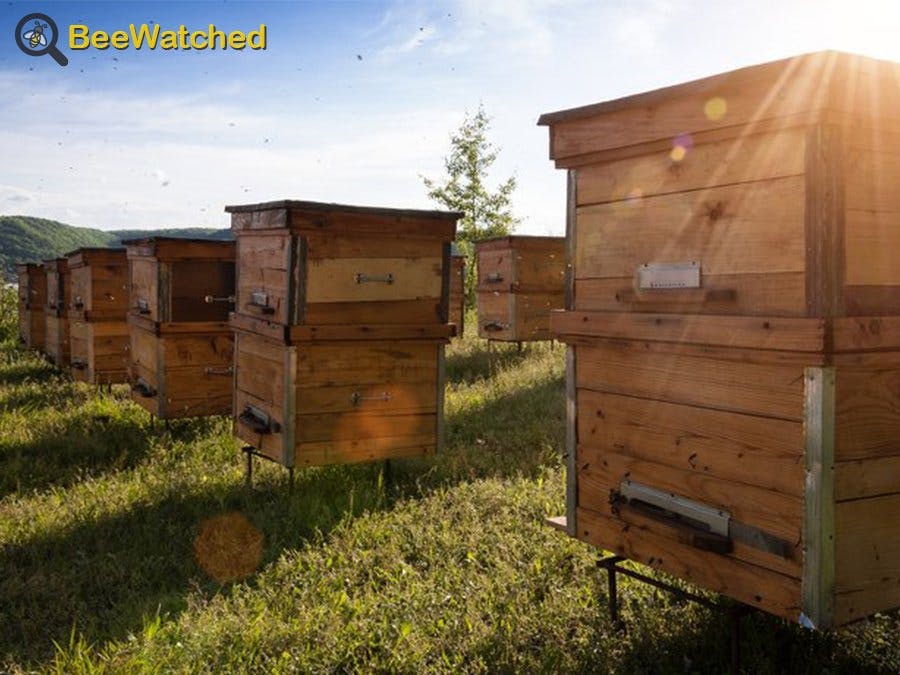
We are a team of two students in Engineering School (Polytech Sorbonne) in Paris. We decided, for our project, to help bees that are essential for our planet.
What is our project about ?For several years, beekeepers have noticed a high mortality of their hives. The bees leave hives abruptly without warning signs. That's why we've created a system that controls temperature and humidity inside a hive, to detect any health problem.
This system is connected and the data collected can be consulted online. The system makes a measurement every 40 minutes. Moreover, it's possible to see the battery power level to know when to recharge the system.
How it works ?Prerequisites
Have knowledge in
- Microcontroller programming (C)
- How to read a datasheet and extract the most important data
- UART
- How to design a PCB
- Electronics
How to send data using Sigfox:
- AT Command
- How many message can be sent per day?
- How to build the message? (JSON language)
- Carry out a list of all the needed components (see in the category things) :
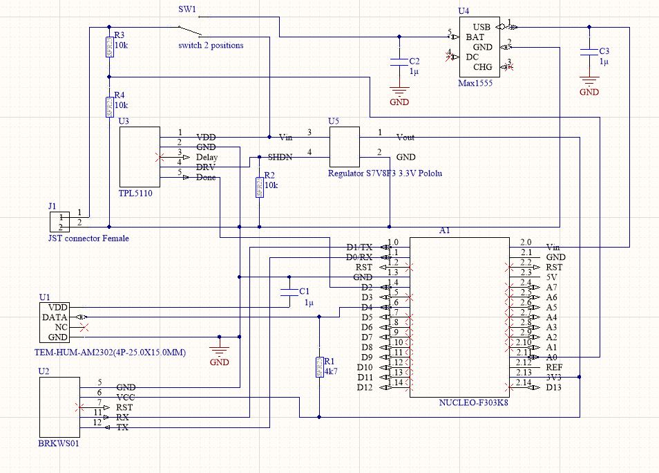
- Battery and regulator for powering the project
- A timer for a very low consumption
- The sensor to measure the temperature and humidity
- A microcontroller, "brain" of the project
- A Sigfox module to send all the data to the network
- An IC to charge the battery via the STM32 nucleo USB
- Carry out a mapping of all the pins used for the project, depending on the technologies used to interpret the data
How to make it work ?Programming the microcontrollerto program the microcontroller you can make it on Mbed Compiler.
Programming the microcontroller STM32 NUCLEO-L432KC in terms of:
- Retrieving data from the sensors
- Converting the data to send using Sigfox
- Configuring the sleep mode of the microcontroller when the Sigfox module does not send message
- Libraries to use
#include "mbed.h"
#include "mbed_dht.h"
- Pinout assignment
DigitalOut myled(LED1);
DigitalOut done(D2);
AnalogIn battery(A0);
DHT sensor(D4,DHT22);
Serial pc(SERIAL_TX, SERIAL_RX);
Serial Sigfox (D1, D0);
- Main
main loop :
 while(1)
   {
       myled = 1;
       done = 0;
       err = sensor.readData();

       /* ************************* */
       /* setting the battery level */
       /* ************************* */
       tempbatt = (2.1)-(battery*3.3);
       tempbatt2 = 0.5-tempbatt;
       niveaubatterie = (tempbatt2*100)/0.5;
       nb = (unsigned char)niveaubatterie;

        /* ********************* */
        /* case without mistakes */
        /* ********************* */
        if (err == 0) {

           // manage the variables of temperature and humidity
           temperature = sensor.ReadTemperature(CELCIUS);
           humidite = sensor.ReadHumidity();
           tAV = (int) temperature;
           hAV = (int) humidite;

           //sent data to sigfox
           Sigfox.printf("AT$SF=%02x%02x%02x\n", tAV,hAV,nb);
           wait(10);
           done=1;
       } else
        /* ****************** */
        /* case with mistakes */
        /* ****************** */
           pc.printf("\r\n\r\nErreur %i \r\n", err);
           myled = 0;
           wait(10);
           myled = 1;
           wait(1);
   }
Initialize the Sigfox module
The BRKWS01 board is the module used to send data on Sigfox cloud. Sigfox is an Iot network created in France, it's work around the world.
The BRKWS01 board requires at least +3.3v, ground and Tx Rx connections.
- 140 messages per days
Next, you can test your module with putty with UART connection. Connect the system in serial mode. the module is controlled with serial AT commands sent on TX / RX pins.
Serial communnication : 9600 bauds, 8 bits
Below is the communication specification and the AT commands to use.
Once the sigfox module connected to PUTTY entered the command "AT" in the command console, you must receive "OK" if everything is normal.
You can consult this link for more explanation.
Then create a sigfox account and fill in the information about the BRKS01.
At first, you can test the connection to the sigfox network by programming a callback to an email address.
Write a message on PUTTY for exemple "AT$SF=0101" and you will receive this message by mail.
How to link Sigfox and Ubidots
- First You have to configured Sigfox callback. We follow this tutorial to structure the Sigfox message on the callback configuration. The programming language is JSON (JavaScript Object Notation).
I have three variables declared :
the temperature : "tAV::int:8" type integer of 8 bits with name tAV.
The humidity : "hAV::int:8" type integer of 8 bits name tAV.
The charge level of the battery type : "niveaubatterie::uint:8" unsigned integer of 8 bits with name niveaubatterie
this the data send by Sigfox BRKS01, received on the backend :
- Then you have to create an ubidots for education account. The token number must be entered in the sigfox callback. Then when the body of your callback is completed, the variables will appear on ubidots.
Above you can see the test results in real condition, we have deposited our product for 48 hours in a beehive.
- You can create SMS or Mail alerts from ubidots, to be notified in case of critical data.
In our case the temperature and the humidity should not be lower than 30 ° C and 60%, otherwise a mail will be sent to warn me there is a problem in the beehive. Moreover the battery should not go below 15% of charge.
- Test the circuit via breadboard
- Design the PCB via an electronic design App like Altium Designer, make it done and solder all the components on it.
After measurements, the circuit consumes:
- 200uA on "shutdown" mode
- 90mA during data transmission by BRKS01 module (approx. 6 sec)
- 20 mA during measurement by DHT22 module
The timer TPL5110 low consumption, allows the circuit to be fed every hour in order to take a measurement, then the regulator returns to "shutdown" mode as soon as the sending ended without errors thanks to its entry "done" activated by the microcontrolle.
The system allows a battery life of about 112 days.
The timer turns on the system every 40 min.
Consumption chart :
- At first take the measurement of the system.
- Next use a CAO Sotfware, we used SolidWorks.
- The box must not exceed a certain size to enter in the hive without disrupting the life's bees.
- The box must have an easy opening.
- Holes on the sides allow a flow of ambient air for measurements.
- Provide a hive attach
Once the plan is complete, you can print your box with a 3D printer.
You can now install your Beewatched in your bee hive!


_1x_bGT19vVAby.png?auto=compress%2Cformat&w=40&h=40&fit=fillmax&bg=fff&dpr=2)
Comments
Please log in or sign up to comment.