In several projects, it is necessary to monitor variables such as lighting level, temperature, ambient pH, humidity and other quantities.
In this process, it is often necessary to monitor a certain amount of samples at different points of space/environment. We can exemplify the illumination of a room.
Depending on the layout of the lamps, the lighting may be different in some places in the room. So we can have several luminance values.
Thinking about this, the need arises to develop a system, capable of collecting data and storing it on a memory card. Its purpose is to perform several samples at each analysis point and store the data on an SD Card.
For this, we will use an Arduino and an SD Card, to make the acquisition of the data and storage in the memory card.
Now, we will present the entire project structure.
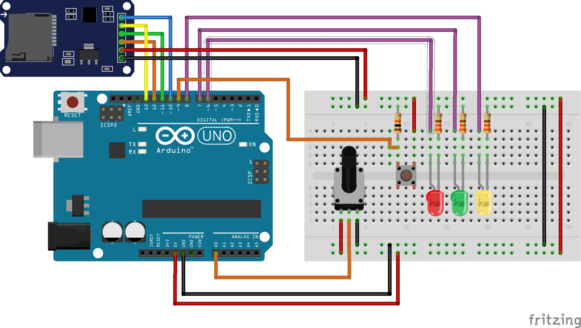
The ProjectThrough of circuit presented in Figure 1, itis possible to see all equipment used to construct the project.
Through the circuit, we use three LEDs. Each LED represents a specific state of the system. Hereafter will be present each function according to each LED:
- Red LED: Used to signal a problem with memory SD Card and its connections;
- Green LED: Used to signal the finish of the process of data collection;
- Yellow LED: Used to signal the process of data collection.
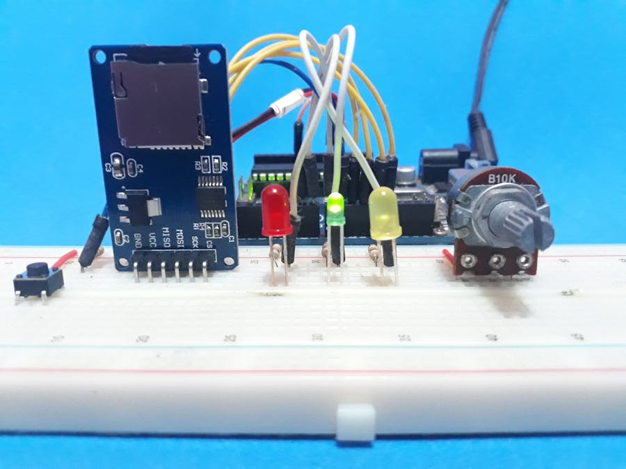
The working of the system is very simple! Before in the void setup, the system will initialize the SD Card and case it is not connected, the system will activate the Red LED to signal fault of the SD Card in the device. The user needs to connect the SD Card and reset the system. The Red LED is presented in Figure 2.
After the verification of the SD Card, the system will initialize and always that the button is pressed the system will collect 10 values of the analog A0 pin and will store in the SD Card.
At this moment, the yellow LED will signal for information at the user that the system is collecting the data, as is presented in Figure 3.
After the data collected, the yellow LED will be deactivated and the green LED will activate to signal the finish of the process, as is presented in the Figure 4.
At this moment, the system waits to be off or if the user presses the button again, more ten values will be stored.
Hereafter will be presented all code used to create this project.
The Logical of the ProgrammingAll code is presented below, but each portion of the code will be explained. In the first portion, are included all the libraries, all pins used in the project will define and are created all variables of the project.
#include <SD.h>
#include <SPI.h>

File myFile;

#define RedLED 6
#define GreenLED 7
#define YellowLED 8
#define button 9
#define AnalogPin A0

int pinoSS = 10; // Pin 53 para Mega / Pin 10 para UNO

unsigned long int tempo_atual = 0; //Variable used to store the current time of code execution
unsigned long ultimo_tempo = 0; //Variable used to store the last value stored in the variable tempo_atual

int DigitalValue = 0;

byte samples = 0, value = 0; //Sample is a variable to count until 10 and value is used count the number of times that user store 10 samples
bool ButtonControl = 0, control = 0;
In the setup function, all pins used are configured like output and input according to the functionality of each connected device. Hereafter, the system will try to initialize the SD Card. If occur any problem, the Red LED will be activated.
void setup()
{
   Serial.begin(9600); // Define BaundRate

   pinMode(RedLED, OUTPUT);
   pinMode(GreenLED, OUTPUT);
   pinMode(YellowLED, OUTPUT);

   pinMode(pinoSS, OUTPUT); // Pin pinoSS like a output

 if (SD.begin())
 { // Inicializa o SD Card
 Serial.println("SD Card pronto para uso."); // Imprime na tela
 }
   else
 {
 Serial.println("Falha na inicialização do SD Card.");
 digitalWrite(RedLED, HIGH);
 return;
 }

}
So, in the loop function, the pin of the button will be read. If the button is pressed, the first condition will be true.
if(pino == 1 && control == 0 && ButtonControl == 0)The text file silicioslab.txt will be opened. And will be printed the message "Sample: " following with value, that represents the number of sequences of readings of ten samples.
Observe in the first condition that variable ButtonControl will receive the value 1. This variable will be used to enable the system to enter in the second condition.
if((ButtonControl == 1) && (tempo_atual - ultimo_tempo >= 1000) && samples < 10 && control == 1)The second condition will be executed and the digital value will be read and saved on the SD Card. It will be read 10 values.
When the value of readings will equal 10, the second condition will be false.
At this moment, the third condition will be true, the Green LED will be activated and the file will be closed.
void loop()
{

          bool pino = digitalRead(button);

         //Condicao para detectar quando o botao e pressionado
         if(pino == 1 && control == 0 && ButtonControl == 0)
         {
             myFile = SD.open("silicioslab.txt", FILE_WRITE); // Create/Open File the txt
             delay(500);
             ButtonControl = 1;
             value++;
             myFile.print("sample: ");
             myFile.println(value);
             samples = 0;
         }

           tempo_atual = millis();

         if((ButtonControl == 1) && (tempo_atual - ultimo_tempo >= 1000) && samples < 10 && control == 1)
         {
           DigitalValue = analogRead(AnalogPin);
           myFile.println(DigitalValue);
           control = 0;
           ultimo_tempo = tempo_atual;//Store the actual time
           samples++;
           digitalWrite(YellowLED, HIGH);
         }

         if(samples >= 10)
         {
           digitalWrite(YellowLED, LOW);
           myFile.close();
           ButtonControl = 0;
           digitalWrite(GreenLED, HIGH);
         }

         control = control ^ 1;
}
After this, the system waits while the user presses the button again. If the button was pressed, a new block often reading will be made again.
Therefore, the system is simple and can be implemented in several projects used for monitoring and data collected for analysis.
Our last article published in the HacksterIn our last article, we teach how to detect a fault in DS18B20 temperature sensor in real-time during code execution. See the result in Figure 5 and access through the following link: Access last article!
Thanks to the PCBWay for support the our YouTube Channel and produce and assembly PCBs with better quality.
The Silícios Lab thanks UTSOURCE to offer the electronic components.


Comments
Please log in or sign up to comment.