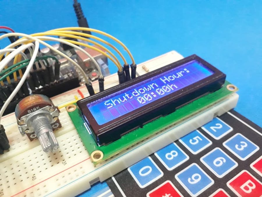
In the third part, we implement several steps to create several functions as ReadKeyPad, AdjustHour, and ActivationHour.
Through these functions, we've created the first part of our project. The second part can be accessed in the following link: Access the second part of the article.
Now, we implement the new features of the project.
Development ProjectThrough the implemented functions until now, in this third part, we'll implement new features to better the quality of our project.
Hereafter, will present the new features:
- Implement DeactivationHour() function;
- Implement a logical system to compare the clock to activate and deactivate the device connected in the relay;
- Implement signalization to indicate the key pressed.
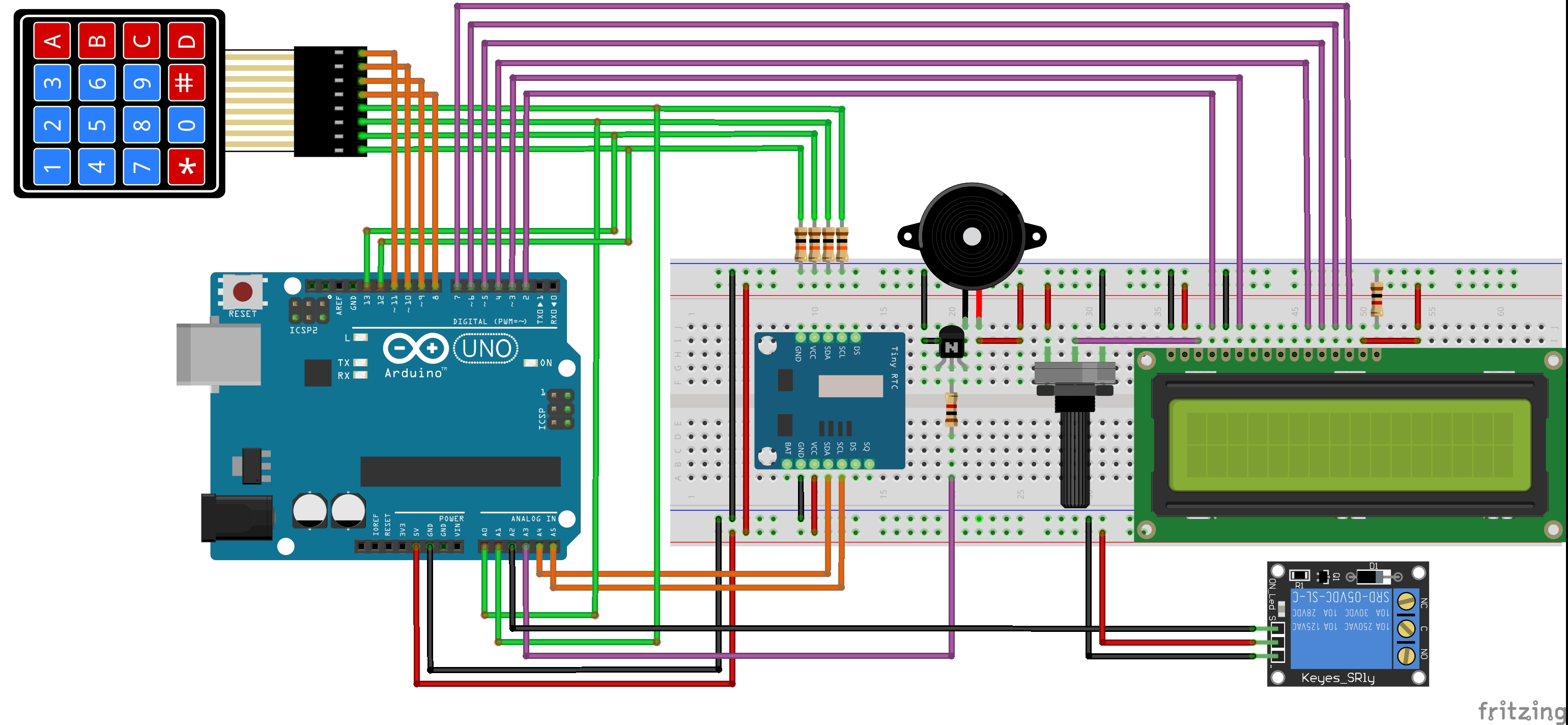
Based on the new features, was implemented a new circuit as is shown in Figure 2.
Firstly, we'll present the new function DeactivateHour(). This function is equal to the function ActivateHour.
The single difference is the EEPROM positions used to save the hours and minutes to deactivate the device.
Now, we'll see the DeactivateHour function.
Implementing the DeactivateHour Function()Through this code, you can see that code is equal at ActivateHour function. All logical programming is presented in the second part - Access the Second Part.
void DeactivationHour(void)
{
   int times[6];
   int  DadosTempo[7];
   bool controle = 0;
   bool EstadoSobe = 0, EstadoDesce = 0;
   byte cont = 0;
   byte number = 0;
   int digitos[6];
   byte PosCursor = 0;
   bool Validate = 0;

   lcd.clear();

         for(byte i = 0; i < 6; i++)
         {
           digitos[i] = 0;
         }

         do
         {
             lcd.setCursor(0,0);
             lcd.print("                ");
             lcd.setCursor(1,0);
             lcd.print("Shutdown Hour:");
             lcd.setCursor(0,1);
             lcd.print("                ");
             lcd.setCursor(5,1);
             lcd.print("00:00h");
             PosCursor = 5;
             Validate = 0;

           do
           {
             number = ReadKeyPad();
             delay(100);

             if( (number >= 0 && number <= 9) && (controle == 0) && (cont < 4) )
             {
               digitos[cont] = number;
               cont++;
               controle = 1;
               lcd.setCursor(PosCursor,1);
               lcd.print(number);
               PosCursor++;

               if(cont == 2 || cont == 4)
               {
                 PosCursor = PosCursor + 1;
               }
             }

             if(number == 16 && controle == 1)
             {
               controle = 0;
             }

             if(number == 12)
             {
                 for(cont = 0; cont < 4; cont++)
                 {
                   digitos[cont] = 0;
                 }

               lcd.setCursor(0,1);
               lcd.print("                ");
               lcd.setCursor(5,1);
               lcd.print("00:00h");
               PosCursor = 5;
               cont = 0;

               for(int i = 4; i < 6; i++)
               {
                 times[i] = 0;
               }

             }

           }while(number != 13);

           times[4] = (digitos[0]*10) + digitos[1];
           times[5] = (digitos[2]*10) + digitos[3];

           EEPROM.write(3, times[4]);
           EEPROM.write(4, times[5]);

           if((times[4] < 0 || times[4] > 23) || (times[5] < 0 || times[5] > 59))
           {
             lcd.clear();
             lcd.setCursor(4,0);
             lcd.print("Invalid");
             lcd.setCursor(6,1);
             lcd.print("Hour");

             delay(2000);

             Validate = 1;
             lcd.clear();

             lcd.setCursor(0,0);
             lcd.print("                ");
             lcd.setCursor(1,0);
             lcd.print("Shutdown Hour:");

             lcd.setCursor(0,1);
             lcd.print("                ");
             lcd.setCursor(5,1);
             lcd.print("00:00h");
             sprintf(tempo, "%02d:%02dh", 0, 0);
             PosCursor = 5;

             cont = 0;

             for(cont = 0; cont < 4; cont++)
             {
              digitos[cont] = 0;
             }
           }
         }while(Validate == 1);

             do
             {
               number = ReadKeyPad();
               delay(200);
             }while(number != 16);
}
The single difference is the EEPROM positions used to save the hours and minutes, as was commented anteriorly.
EEPROM.write(3, times[4]);
EEPROM.write(4, times[5]);
Hereafter will be presentedon the screen when the function is executed in Figure 3.
In this screen, the user will configure the hour that your device will be deactivated. After the user inserts the hour, the system will validate as is shown in the second part of the project.
Right after that, the system will return for the void loop function and execute the block code.
When the 73 value is saved in position MEMORY, the values stored in the EEPROM position 1, 2, 3 and 4 are saved in the two vectors: TimeActiveDevice and TimeDeactiveDevice.
These two vectors are used to store the timer to active and deactivate the device connected in the relay.
void loop()
{
   if(EEPROM.read(MEMORY) != 73)
   {
     AdjustTime();
     lcd.clear();
     ActivationHour();
     lcd.clear();
     DeactivationHour();
     lcd.clear();
     EEPROM.write(MEMORY, 73);

     TimeActiveDevice[0] = EEPROM.read(1);
     TimeActiveDevice[1] = EEPROM.read(2);
     TimeDeactiveDevice[0] = EEPROM.read(3);
     TimeDeactiveDevice[1] = EEPROM.read(4);
   }

   DS1307.getDate(DataTime);
   SegAtual = DataTime[6];

   if(ReadKeyPad() == 10)
   {
     AdjustTime();
     lcd.clear();
     ActivationHour();
     lcd.clear();
   }

   if(abs(SegAtual - SegAnt) >= 1)
   {
     sprintf(tempo, "%02d:%02d:%02d", DataTime[4], DataTime[5], DataTime[6]);
     sprintf(data, "%02d/%02d/%02d", DataTime[2], DataTime[1], DataTime[0]);
     lcd.setCursor(4,1);
     lcd.print(tempo);
     lcd.setCursor(4,0);
     lcd.print(data);
     SegAnt = SegAtual;
   }

   //Active and Deactive the device according to the time
   if(DataTime[4] == TimeActiveDevice[0] && DataTime[5] == TimeActiveDevice[1])
   {
     digitalWrite(RELAY, LOW);
   }

   if(DataTime[4] == TimeDeactiveDevice[0] && DataTime[5] == TimeDeactiveDevice[1])
   {
     digitalWrite(RELAY, HIGH);
   }
}
Therefore, after this, the system will present the hour and date in the LCD. And, hereafter, will compare the current hour and minute with values of the vector.
In this way, the relay will be activated or deactivated based on the hour of the day.
Finally, we will implement a buzzer, to indicate that a key was pressed by the user.
Buzzer to indicate key pressedThe Buzzer is very important to indicate that the key was pressed by the user. Often, the user is not sure if the value was entered. In this way, the buzzer will indicate that the key has been pressed.
byte ReadKeyPad(void)
{
 byte teclado[4][4] = {
 {1,2,3,10},
 {4,5,6,11},
 {7,8,9,12},
 {14,0,15,13}};
   byte coluna[4] = {8,9,10,11};
   byte linha[4]  = {12,13,14,15};
   bool tecla;
   byte digito_tecla = 16;
   for(byte y = 0; y <= 3; y++)
   {
     digitalWrite(coluna[y], LOW);
   }
   for(byte y = 0; y <= 3; y++)
   {
     digitalWrite(coluna[y], HIGH);

       for(byte x = 0; x <= 3; x++)
       {
           tecla = digitalRead(linha[x]);
           if(tecla == 1)
           {
             digito_tecla = teclado[x][y];
               digitalWrite(BUZZER, HIGH);
               delay(100);
               digitalWrite(BUZZER, LOW);
             return digito_tecla;
           }
       }
    digitalWrite(coluna[y], LOW);
   }
   return digito_tecla;
}
Inside of for loop, the Buzzer is actuated for 400 ms to signalize for the user.
Now, you'll see the working of the relay when is activated according to the time.
Activation of the relayTo perform the test of the relay activation, the relay was programmed to be activated at 10:46 AM. As is possible to see in Figure 4, the relay is deactivated.
This status is represented by the green LED.
Now, in Figure 5 the relay is activated and the green LED is actuated to represent the activation of the relay.
Finally, we have been able to implement the main functionalities to carry out the activation of the relay at the scheduled time.
Now you can use this entire project to apply to devices that need to be triggered at a scheduled time.
New features will soon be created for our device.
AcknowledgmentThanks to the PCBWay for support the our YouTube Channel and produce and assembly PCBs with better quality.
The Silícios Lab thanks UTSOURCE to offer the electronic components.


Comments
Please log in or sign up to comment.