Home security systems can be so expensive these days. It would be great if there was an easier, cheaper way to protect your home while you are away. Thankfully, you have arrived at the right place. This security-based project was chosen due to its continuous practicality. As long as there are houses whose owners like to monitor the activity in and outside, there is a need for a system to record and document that information. This project outlines how you can use a Particle Argon, IFTTT, and Google Sheets to create a simple, cheap home security system.
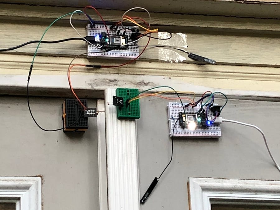
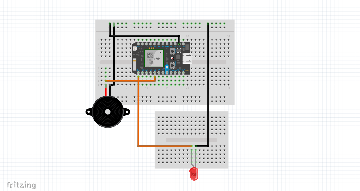
This project requires three Argon boards with three different tasks. The first of which, Argon 1, is a laser emitting circuit, shown below. This Circuit contains a buzzer and a laser emitting diode.
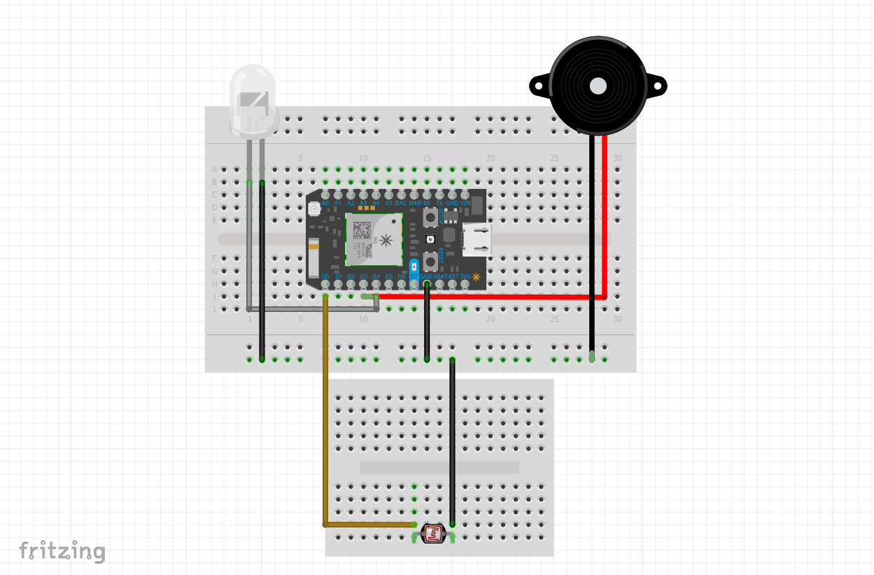
The second circuit, Argon 2 is the laser receiving circuit, shown below. Consisting of a photo resistor, led, and buzzer this Argon communicates bidirectionally with both Argon 1 and Argon 3.
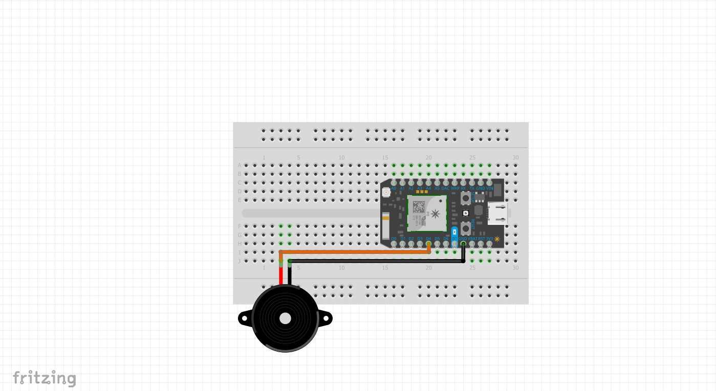
The final circuit, Argon 3, the data acquisition and transmission circuit is shown below. This circuit is much more simple, consisting of only an active buzzer. This Argon communicates with Argon 2 and IFTTT.
It is recommended that Argon 1 and 2 are each powered by a 3.7V Lipo battery with an amperage around 1000mah. For the sake of convenience and demonstration these items were not used in this project. The use of such batteries would allow the system to be compacted into a smaller, eye friendly application.
Project Construction Manual1. Laser Transmission Circuit- Connect Particle Argon to the main breadboard
- Connect Argon 3v3 to positive power rail and Argon ground to negative power rail
- Connect laser emitter to small breadboard and jump laser ports to power, ground, and pin D0, respectively
- Connect buzzer to main breadboard and jump buzzer ports to power, ground, and pin D4, respectively
- Connect Particle Argon to the main breadboard
- Connect Argon 3v3 to positive power rail and Argon ground to negative power rail
- Connect photoresistor to small breadboard and jump laser ports to power, ground, and pin D0, respectively
- Connect buzzer to main breadboard and jump buzzer ports to power, ground, and pin D8, respectively
- Connect led to main breadboard, with the positive lead in pin D9, the negative lead in a row on its own, and a resistor jumping the negative lead to the ground rail
- Connect ParticleArgon to the main breadboard
- Connect Argon 3v3 to positive power rail and Argon ground to negative power rail
- Connect buzzer to main breadboard and jump buzzer ports to power, ground, and pin D4, respectively
**Note: active or passive buzzers may be used in the setup
Circuit CommunicationIFTTT was used in order to import data into a google spreadsheet and receive notifications on a cellular device.
Link to view collected data in Google Sheets:
https://docs.google.com/spreadsheets/d/1iLlc2VhV77jcftnp6jHIz_D752fxZX12Th8jbhpNMkA/edit?usp=sharing


_zhWsCcSEcl.jpg?auto=compress%2Cformat&w=48&h=48&fit=fill&bg=ffffff)


Comments
Please log in or sign up to comment.