The overall aim of this project was to use an IOT device to drive a continuous rotation servo motor to dispense specified amounts of food at specific daily intervals. Initially to be driven by weight readings from a load cell adapted from a kitchen scale, the final implementation utilized IFTTT-driven publications from a Google Calendar to drive a dispensing servo at designated times.
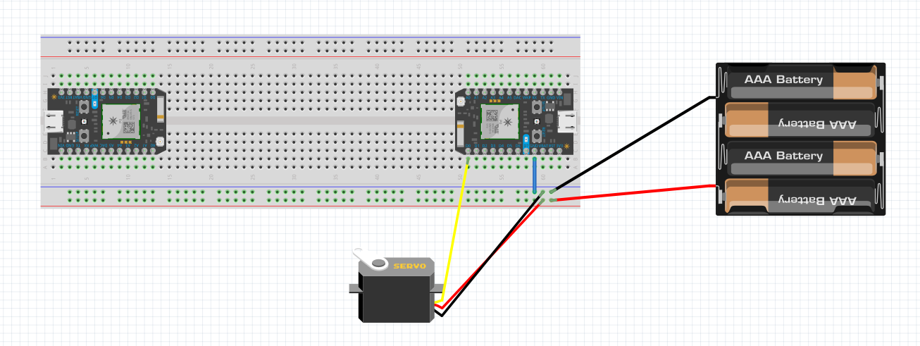
Initial Concept and ImplementationThe first Photon (P1) was meant to take a weight reading from the kitchen scale and publish a variable to the Particle cloud. The second Photon (P2) was meant to subscribe to this variable and operate the servo.
Servo:
The first hurdle to overcome was to decide on a container, and a quick Amazon search yielded a set of simple cereal dispensers.
This led to deciding on servo implementation. It was quickly realized that the servo contained in the particle maker kit only rotated 180 degrees. Three wires were removed from the potentiometer, and two 1000 ohm resistors were soldered in place of the variable resistor. Although continuous rotation of the servo was successful, the engaging gear of the servo possessed a flat surface preventing 360 degrees of rotation. This engaging gear was replaced by another that had a full gear of splines and no flat surfaces. Another problem reared its head in the form of the top cover would not fit over the new gear even after slight modification. This coupled with another problem of each attempt to replace the back cover broke the solder joints due to the small wires and tight confinement. Ultimately, the task of modifying the servo was abandoned for a high-torque continuous servo purchased from Amazon.
With the servo problem situated, it was then assumed that the new servo could be plugged directly into the same pins on the Particle Photon. This was a sorely mistaken assumption, which resulted in a fried Photon when turned on. With the purchase of a new Photon, the project was back on track. Additionally, thorough research taught that the high-torque servo required an external power source.
Weight Scale:
Focus then transitioned to weight scale operation, and how that would incorporate into the overall project. An analog to digital converter (ADC) and I2C shield were purchased from ControlEverything.com.
The ADC was to convert the analog voltage from the weight scale load cell to digital voltage:
This digital voltage was to be input into the photon via the I2C shield. The positive strain gauge output (green wire), and negative strain gauge output (white wire) were connected to two of the ADC's analog inputs. The strain gauge was powered externally by the scale's original AA batteries through the breadboard:
The code to be used for converting the analog load cell results into a usable digital readout by the ADC was obtained from the community library ADAFRUIT_ADS1X15 through the Particle IDE. After numerous attempts, followed by further research into load cell/ADC interfacing, it was determined that the signals generated by the load cell compression were too small for the ADS 1115 to be properly utilized. Attempts were made to utilize the Comparator, Differential, and Single-Ended versions of the code, but none were successful in returning useful counts to the digital inputs of P1.
In an attempt to demonstrate a proof-of-concept for the design, the outputs of the load cell were connected to the analog inputs of P1. The variables "analogvalue1" and "analogvalue2" corresponded to the A0 and A1 pins, respectively. The difference between the A0 and A1 readings was set as "analogdiff", and load on the cell was incrementally increased to determine if load variations could be sensed:
As shown in the video above, increasing loads produced measurable results, albeit not at a fine enough resolution to meet project objectives. If the above video is placed in Fullscreen, the average "analogdiff" value can be observed changing from 1.2 with an unloaded scale to -2 with one book, -6 with two books, and peaking at -6.5 with three books.
In an attempt to produce a usable signal at smaller load variations, an LM358 Op-Amp was used to process the output signal from the load cell. While highly sensitive to load variations, the LM358-processed signal was ultimately too corrupted by noise to provide usable data on load variations.
Simultaneously, coding work was being attempted to operate the servo via mobicle.io. Functions were added to the code to allow for "on" and "off" buttons to cue the servo from a telephonic mobile device. Unfortunately, the coding never moved beyond any errors when verified or attempted flashing. The combination of these issues and the scope of details to be addressed regarding load cell signal processing resulted in the search for a more reliable method of implementation.
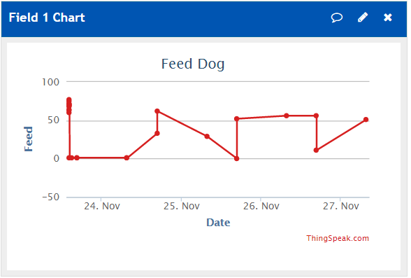
Secondary Concept and ImplementationThis method involved utilizing the If This, Then That (IFTTT) website to set specific dates and times the servo was to be in operation for a specified degree of rotation. The event "Feed Dog" was added to a Google Calendar. Linking an IFTTT applet to this calendar causes an event to be published to the Particle cloud within fifteen minutes of the even occurring. Subscribing to the event signals P1 to execute the servo operation, while P2 registers the event and plots it as a data point on a simple graph on thingspeak.com.


Comments