


Hardware components | ||||||
 |
| × | 2 | |||
| × | 1 | ||||
| × | 2 | ||||
| × | 1 | ||||
 |
| × | 1 | |||
| × | 1 | ||||
Software apps and online services | ||||||
 |
| |||||
 |
| |||||
This project will be explained in four main parts.
- Car operation.
- RF communication.
- Electromyography signal acquisition.
- DSP with MATLAB.
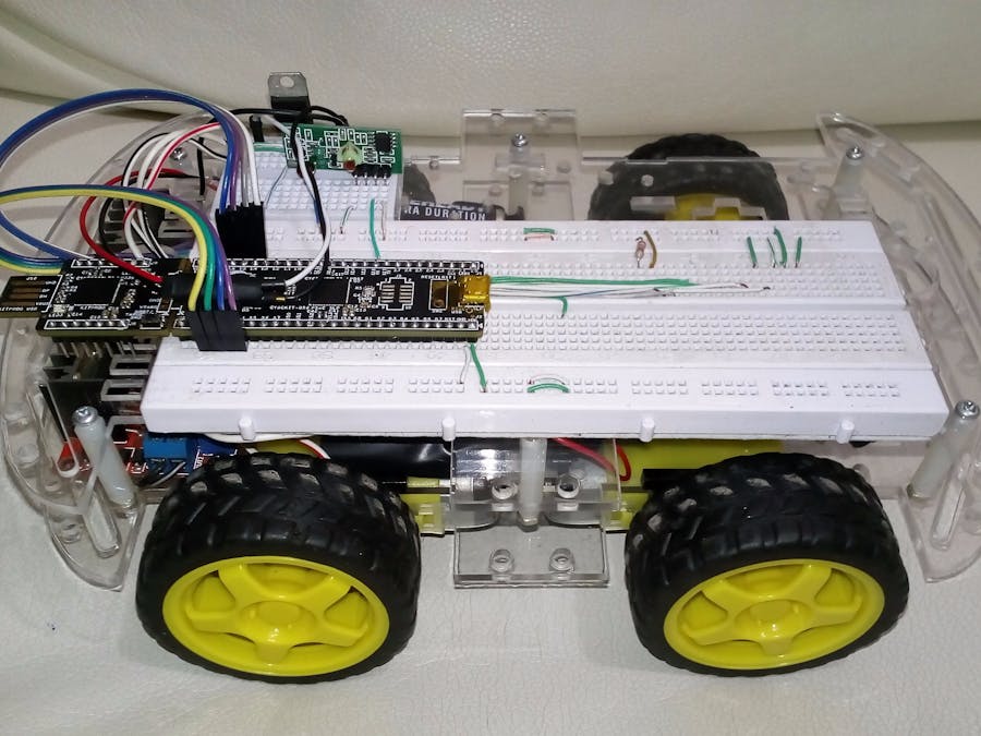
We started with the car chassis, for this project we employed 2 “packages battery” with 5 batteries each one as is shown in the picture, each package is used to provide energy to L298N drivers and LM7805 regulator, this was done due to avoid the amperage problem.
On top the car has a PSoC 5 as main module, its respective LM7805, a receiver RF module and the enough connections to generate different states in the L298N, this was done to move the car to right, left, front or stop. (Code PSoC Car Receptor)
In this case we have chosen the ASK modules to make the radio frequency communication between the computer and the micro-controller (uPc) which drives the car. These modules are too easy to connect, we just have to supply the voltage required, in this case we've used 9v, and we had to make a kind of antenna with a wire whose height must be 17 cm. This antenna is made one for each module (transmitter, receiver), if we do this, the communication between modules will be stronger.
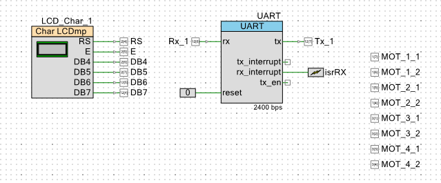
The receiver module is connected to the micro-controller which drives the car (uPc2), and the data pin has to be connected to the Rx pin of uPc2.
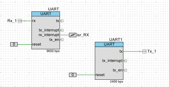
The transmitter module is connected to the micro-controller which sends data from MATLAB (uPc1), and the data pin has to be connected to the Tx pin of uPc1. With our modules was necessary to solder the antenna to a specific pin on the module.
The RF communication part in the code made for each micro-controller was made at 1200 bauds, what makes sense if we know that these type of modules can't work at higher speed.
The data was sent as any other UART communication, so don't be afraid, this is the same. If you want, you can build a protocol with some kind of "Checksum" to avoid corrupt data.
3- Electromyography signal acquisition.Normally electromyography is used to test the health of our muscles, but in this project we're just not going to test them, we're going to use them to move a car, but to do that we need to acquire a signal, something which we can work and treat it like any other electrical behavior . Fortunately we have the Advancer technologies muscle sensor v3.0 which makes all the job, and we just need to plug the audio connector to our computer as being a microphone hardware. We can adjust the gain too, though the signal read in MATLAB is a too low voltage one.
Now we must to know, how to connect the electrodes to acquire a signal, but first it's too important understanding how this works or at least what we can read through the device.
Reading frequency from the muscles may be something really complicated, or harder because we're looking for 4 different signals to drive a car remotely, for this reason we have chosen read the amplitude which is easier because we can read different amplitudes with the movements of the hand. We have placed the electrodes in this way, because here we would be reading the differential vibration of the muscles referenced to the one which is placed near to the hand.
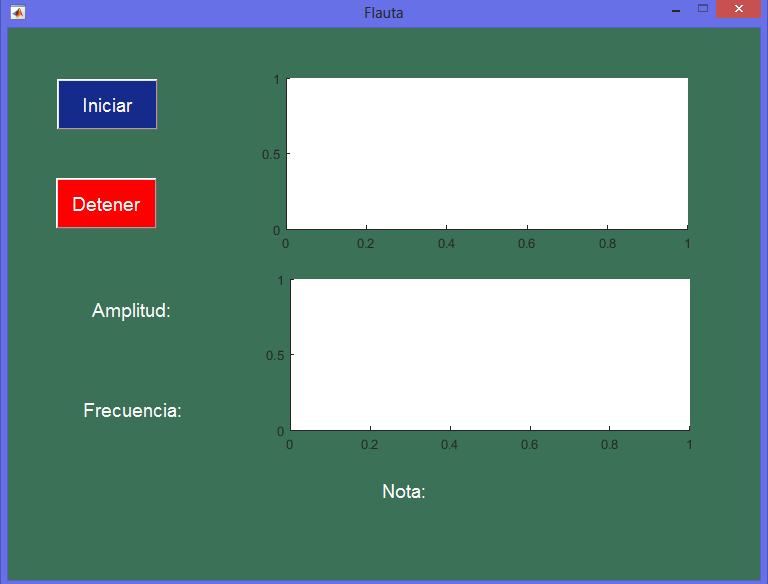
Yes, here we need to use MATLAB, to see if we are reading the right signals or what we need to acquire. How to do it? It's too easy, we just create a code in MATLAB which will be reading audio signal from the "microphone" (you can type in the MATLAB help tool, this function "audiorecorder" there you will find an useful example to record from the microphone with MATLAB. However, we have added the MATLAB code below). The code must be made preferably with GUI, because we need to see like it would be in real time graphically and numerically the data acquired, or the signal which has being read.
4- DSP with MATLAB (Digital signal processing)In this part we need to analyze the amplitude that we can read with the device and our fingers movements or the whole hand. We need to try, and choose which muscle will be one of the four commands to be sent to the car.
Once we have chosen the four signals (just looking for amplitudes) we can build a representative interval of each one because signals have little changes and aren't the same all the time. What we did was just put a letter (char) when the amplitude was in the interval, and immediately use the serial port from MATLAB and send to uPc1 the char which could mean left, right, advance or stop.


Comments
Please log in or sign up to comment.