


Hardware components | ||||||
 |
| × | 1 | |||
 |
| × | 1 | |||
Software apps and online services | ||||||
| ||||||
Have you ever wanted a high-speed video link to the raspberry pi? This project is specifically done to address this need. There is a high-speed camera link on the pi which receives camera data though MIPI CSI protocol. However, the details of this protocol are under NDA, and until recently, not much information could be found through publically available documents. But a draft of the specification can be found by simply googling this keyword: "mipi csi-2 specification".
This draft is close enough to what we need to know in order to use it in our applications. on the other hand, the MMAL library on the pi and the MIPI subsystem modules from Xilinx provides all the building blocks needed for doing this project. The MMAL library is an abstraction layer for working with the media pipelines of the raspberry pi. A great source for learning about this library can be found here. On the other hand, the Xilinx CSI-2 TX subsystem is an IP core that sits in the FPGA section of the Zynq device and converts the AXI4 Video stream data into the MIPI CSI-2 packets. The Ultra96 evaluation board is equipped with an ultrascale+ Zynq chipset which supports the MIPI electrical standards natively.
So in this project, I decided to create a simple demo of all these parts put together to enable the lovely Pi to capture images from a Xilinx FPGA. It's worth noting that even though this project is focused on image data, the same arrangement can be used for transferring arbitrary information to the Pi which makes a whole array of applications possible.
How does it work?For a detailed description of the protocol, one should refer to the draft document mentioned above. In a nutshell, MIPI is a multilayer single directional data-link between a peripheral and the processor which was originally designed as a standard of communication for the mobile phone industry. In the lowest layer, the MIPI-DPHY protocol defines the electrical link between the peripheral and the processor.
D-PHY defines a differential link with two main operational modes, High Speed (HS) and Low Power (LP). The image data is transmitted in the HS mode while the transitions between HS and LP also represent different meanings on the pipeline ( Detail is to be found in the D-PHY documents). Camera Serial Interface (CSI) sits on top of the physical layer and defines pixel and timing data that are required for implementing a digital video interface.
The data are transferred in the form of packets which are contained within a Start of Transmission (SoT) and End of Transmission (EoT) states (Defined in PHY). There are two types of packets, namely, short and long packets. Short packets are utilized for transmitting timing information (start and end of frame and lines) as well as custom user-defined states. While short packets do not contain a payload field, a long packet may contain an arbitrary number of payload bytes defined by a Word Count (WC) field in the header.
The type of information in the data field is defined by a unique 6-bit number in the header of the packet. Furthermore, up to four virtual channels of information may be defined over a single physical connection. This channel is also identified by a 2-bit section in the packet. As mentioned in the CSI specs, a receiver must support all the standard defined data types in the spec sheet while the transmitter may only implement one of them. These data types are:
- Raw7-14: This is mostly used for transferring Bayer images as well as non-image embedded data (The kind of format that we can use to send arbitrary data to the Pi)
- Different Variants of RGB Data
- Different variants of YUV Data
For image data, a frame must start with an FS packet and end with an EP one and between these two short packets each image line must be transferred with a single long packet (Theis constraint does not hold in case of user-defined data). Furthermore, between each line, an optional pair of Line Start (LS) and Line End (LE) short packet may be used.
The parameters of the Xilinx IP block and libraries and the modules in the MMAL library provide the APIs needed for setting these parameters which we will see in the following sections.
The Hardware ArchitectureIn this project, we use a Test Pattern Generator (TPG) block for producing the AXI video traffic. The output of this block is then fed to the CSI-TX-Subsystem IP which handles all the required steps for converting it into CSI signals. The overall design is illustrated in the following image:
Moreover, the IPs are configured as follows:
Based on the product guide for the CSI subsystem, the word count, data type, and the virtual channel parameters should be set using the tusr and tdest fields of the input axi-stram to the csi_ts block:
For this example, the data_type has been set to 0x24 which corresponds to RGB888 format, and the WC is set to 1280x3=3840. Furthermore, here we use the virtual channel zero for transferring the data.
After synthesizing the design and exporting the hardware, we should configure and activate the blocks in the Vitis:
As mentioned in the introduction, the Raspberry Pi uses the MMAL library for defining the image pipeline. In this project, three main blocks have been utilized.
A rawcam component receives the CSI signal and extracts the RGB data. This data is then made available by the output port of the rawcam component which is either saved into a file (In callbacks generated by the component) or is linked to an ISP for converting it into a proper format to be sent to the renderer. ISP is also capable of performing other functions such as White Balance and Black Level correction. Finally, the renderer displays the image on the monitor. This implementation has been done based on the raspiraw application.
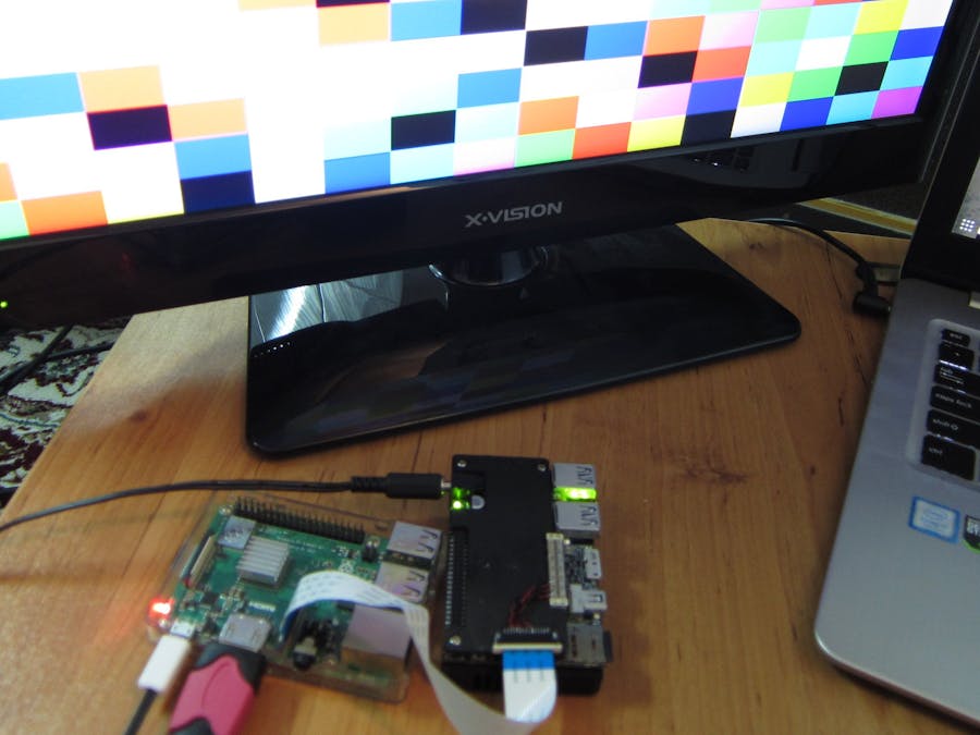
Finally, after connecting the proper pins of the Ultra96 to the corresponding pins on the pi, the test patterns can be seen on the monitor as seen in the following images:
This project is a base for many other cool projects. For example, the images from the global shutter camera that I connected to the Ultra96 in this blog can be processed in the FPGA and then transferred to the pi to be utilized by the upstream applications. This can offload the Pi and also opens the possibility of utilizing other images sensors or even composite or HDMI inputs.
On the other hand, the RAW8 format of the CSI interface can be exploited for transferring custom datatypes to the pi which can be used for cool projects. For example, the FPGA can read a really fast ADC to convert the pi into a capable digital oscilloscope and logic analyzer.
I hope this project can make the vague world of MIPI based systems a little clearer and would inspire people for making cool projects and maybe sharing them with us here.


Comments
Please log in or sign up to comment.