


Hardware components | ||||||
 |
| × | 1 | |||
 |
| × | 1 | |||
 |
| × | 2 | |||
 |
| × | 1 | |||
 |
| × | 1 | |||
Software apps and online services | ||||||
 |
| |||||
Hand tools and fabrication machines | ||||||
 |
| |||||
Having to do a project in a college course and not having experience working with the Raspberry Pi, we decided to make a simple project using an OLED display and 2 push buttons.
This project shows different displays, by pushing the 2 existing buttons, one for going forward and the other one for going backwards.
We implemented 4 types of displays for screening different information. In the first one we introduced ourselves and project title. The second one contains a RaspberryPi Logo. Continuing with the third, it displays the current date and time with updates. At last, we decided to show some information about the local address, showing the IP, with the subnet mask and the broadcast. Everytime we want to switch between displays, we just press the buttons for skipping or going back to the one we desire.
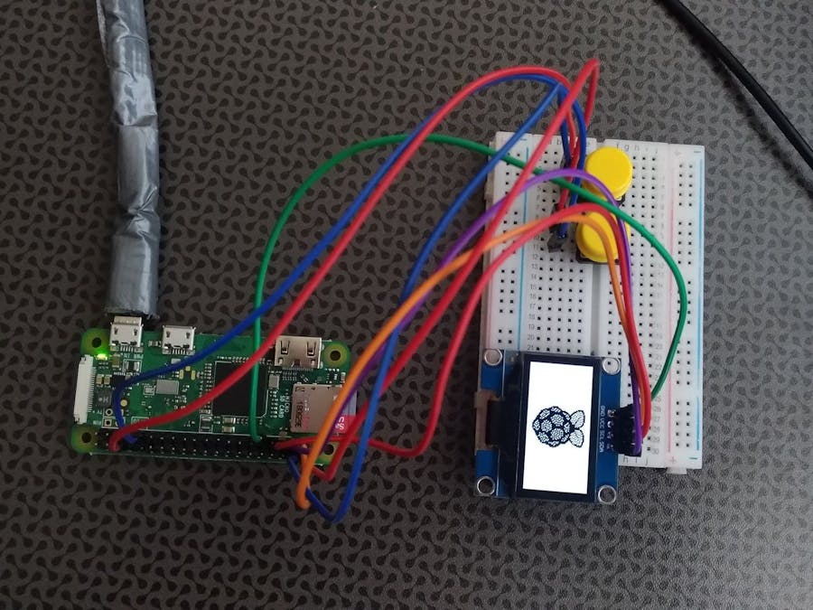
IntroFor this project you will need Raspberry Pi Zero Wifi, an OLED 1.3" 128x64 pixel display and two push buttons 12x12x7.3. The OLED we are using for this project has white pixels and uses an I2C interface which only requires four wires to be connected to the Pi.
OLED Display SetupThis kind of display has four pins, two are power (VCC and GND) and two are for the I2C interface (SDA and SCL). If you bought something similar to the one in the photo above, you may need to solder the pins before you get started.
Also, before starting the project, make sure you have an SD card(min. 8GB) with the latest Raspbian image.
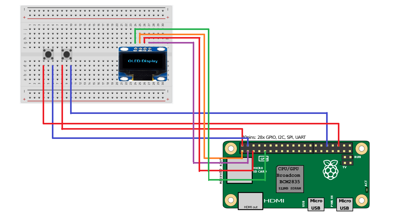
The four pins of the display are connected to tha Raspberry Pi through a breadboard, as it is described below:
OLED GPIO
GND 9 (ground)
VCC 1 (power)
SCL GPIO3 (SCL I2C)
SDA GPIO2(SDA I2C)
If the I2C interface is disabled by default you need to enable it by running : sudo raspi-config. With the I2C library installed, use the following command to find the module on the I2C bus: i2cdetect -y 1
Each button has one pin connected to power on Raspberry Pi and the other Pin connected to one GPIO pin.
The button in the left has one pin connected to power and the other one connected to GPIO16.
The button in the right has one pin connected to power and the other one connected to GPIO12.


_3u05Tpwasz.png?auto=compress%2Cformat&w=40&h=40&fit=fillmax&bg=fff&dpr=2)
Comments
Please log in or sign up to comment.