

Hardware components | ||||||
 |
| × | 1 | |||
 |
| × | 1 | |||
Software apps and online services | ||||||
| ||||||
 |
| |||||
Many times and especially when we want to go on a trip, one of our concerns is to leave the house or apartment totally alone, our biggest concern is to know if there is an intruder inside our house, or simply to control a light remotely from our cell phone to simulate That we are there...
In the investigations that I realized I found several ways but here I will explain the simplest and the one that at the moment I use for this purpose.
Materials- Wemos D1 mini (ESP8266-12)
- USB-Serial Brigde (FT232RL)
- Relay Module
- PIR Sensor
- Smartphone + Blynk App
- Breadboard
- LED
- Connectors
What you first need to know is that we are going to use the Arduino IDE to program the Wemos D1 mini card.
If you have a wemos d1 mini you will realize that it already has a built-in USB-Serial jumper, but I had a lot of problems trying to install the drivers and still did not, so I had to choose to use a separate USB-Serial, connections with the Wemos we will speak later...
Preparing Necessary Software1. We will need to download the Arduino IDE in the latest version, you can do it from here: https://www.arduino.cc/en/Main/Software
2. Add ESP8266 board:
Inside the arduino IDE we go to File - Preferences, in Manager of Additional URLs of Boards we will place the following link and click in the button OK.
http://arduino.esp8266.com/stable/package_esp8266com_index.json
Now go to Tools -> Boards -> Boards Manager and in the Type drop-down select Contribution:
Here we select ESP8266 by ESP8266 community and click to install (I already have it installed by which leaves off the option to install).
It is necessary to remember that, before initiating the programming, choose the correct board.
Change the upload speed to 115200 baud. We already have installed the board Wemos D1 mini correctly in Arduino IDE. Before proceeding to the next step, let's talk a little about Blynk:
Blynk is a platform for ios and Android that allows you to control programmable boards on arduino and Raspberri Pi through internet. The interface is very simple and it works dragging and dropping the components you want to use and start programming!
In my personal opinion this app is one of the most easier platform for IOT in the market, better personalization and easy to use. Then for this application we will use the Blynk platform which is fully compatible with the ESP8266 boards.
The Blynk application can be downloaded directly from the Google Playstore.
Install the Blynk library for ESP8266:Download the library: https://github.com/blynkkk/blynk-library
Go to Program-> Include library-> Add library.zip
Here you will find the library you just downloaded and click on "Open"”. We have completed the preparation of the necessary software for the programming our application. Let start with the basic example in the library of Blynk for esp8266, go to:
Click on File-> Examples ->Blynk->Boards_WiFi->ESP8266_Standalone:
The example code looks something like this:
The only thing that we will do for now is to change the SSID to the name of your network and your respective password. Now we leave the Wemos program (ESP8266) and then we will pass to the blynk application in our Smartphone.
Blynk AplicationWhen you open the Blynk application, the first window that shows is sign in, I do it through my Facebook account:
The next window is to create a new project, here you can read the QR codes of the applications that someone shared, for this example tap in a new project.
here we need to name the project and choose the corresponding board, in this case the name is "Sec1" and the board is ESP8266, the connection type will be WiFi and tap to create.
This is the interface of Blynk, here we can place all the elements that we need to use for the project.
For the application that we are going to use we need the following:
The button is for status change of the light, from on to off. The LED on the left will be a " sidelight" and will simply be used to know when the light actually turns on or off. The LED on the right will be the sidelight for the motion detector, it will light up and stay on for 5 seconds to indicate movement. Notifications will be used to indicate when there is movement, we want blynk to let us know about this event. The mail block will also be used with the movement event, and what we want is that a email is sent to our personal account every time there is movement.
Let's configure each widget in the application, let's start with the button:
We select the button and what we see is an interface as follows:
The most important thing when configuring the button is to check the associated variable for later reading and do the control.
The activation or deactivation of a PIN on our board can be done directly by choosing the pin through the application and this will by default be high or low, but then there will be a drawback when we want to read the same pin to do some other type of control from the ESP program, it is for this reason that I have chosen to use variables for all widgets, the method is simple, simply associate the widget with a Virtual variable and from the ESP program read the changes from that variable and have greater control over the application.
This way, then, the button we put has the following configuration:
Pin Virtual V0
And its state is changed so that it is not a push button but a switch button. Finally the configuration of the button is like this:
In the same way that we did with the button, we also configured the two LEDs, for the left LED we will configure the virtual pin V1 and for the LED of the right we will configure the virtual pin V2..
The next thing to configure is the notification widget:
We will only put it as high priority and leave it like this, later we will check how it is used.
Finally set up the Email widget, here only place the email to which you want to receive the emails sent by the ESP8266.
Only missing something that is very important, the Token for the application, which is an identification of the application on the server and will be used to match the application of the Smartphone with the corresponding ESP8266, then go to project settings and in the part of AUTH TOKENS check Email all, what the application will do is send the token to the email with which we started session in blynk , now check your email and copy the token:
The email sent by blynk looks something like this:
Copy and paste the token in the line of code of the corresponding example program and it looks something like this:
char auth[] = "5638218d52994ba491f1ceb20fa25ca4";
Full blynk aplication :
Just read this QR code in the blynk aplication.
Programming WemosD1mini(ESP8266)Let's start programming our ESP8266:
The first thing I will do is to define the output that will activate the Relay, in this case I will define as digital output, the D4 pin:
pinMode(D4, OUTPUT);
this inside the void setup method.
What you have to do then is to read the changes of the virtual variable of the button and depending on its values it activates or deactivate the pin.
Thanks to the Blynk library read the changes of the virtual variables is quite simple and is achieved through a method that’s named Blynk Write, there we will put the virtual variable of the button and save its value for control. On the other hand we can also control the LED of the application in blynk that we use as "sidelight" and we assign a virtual variable also, then first define an LED type widget so that blynk recognizes that it is an LED it’s going to control and giving instructions yo it, is defined as follows:
WidgetLED led1(V1);
With this done then you can control the LED from the Blynk_Write method of virtual variable change.
Finally the Blynk_Write method is as follows:
BLYNK_WRITE(V0)
{
 state = param.asInt();
 if (state == 1){
   digitalWrite(D4, LOW);
   led1.on();
 }
 else {
   digitalWrite(D4, HIGH);
   led1.off();
 }
}
Note that if there are more buttons is simply assigned another virtual variable and is done in the same way with another method BlynkWrite, so we can send not only states of a button but data directly from the application or from the server.
We have running the on and off part of Lights, what follows then is to include the motion detector part, what we have to do then is to define an input that will be the output of our PIR sensor:
It will be D7 pin
pinMode(D7,INPUT);
Since we use the notification and email function, it is necessary to create a timer to do tasks from time to time, for example we want the LED "sidelight" of movement, last 5 seconds if there is a movement, also send a notification to the application and send an email notifying the movement. It is for this reason that the SimpleTimer.h library is used for this project, which can be obtained from the internet easily and I will also leave it in the project files.
A system of flags will be used to activate and deactivate the sending of notifications and mails, the most important thing to keep in mind are the lines to send notifications and mails. Let's start with the app notification:
To send notification every time there is a movement we use the following line:
Blynk.notify("Heey....!! Hay movimiento en tu casa!");
We have to keep in mind that there are limits for notifications and they are 1 notification every 15 seconds, nothing else.
And finally to send an email every time there is movement we use the following line:
Blynk.email("Subject: PIR Sensor", "Hay movimiento en la casa...");
This line will automatically send an email to the address we set in the application widget.
Finally I leave the arduino program :
#define BLYNK_PRINT Serial    // Comment this out to disable prints and save space
#include <ESP8266WiFi.h>
#include <BlynkSimpleEsp8266.h>
#include <SimpleTimer.h>
// You should get Auth Token in the Blynk App.
// Go to the Project Settings (nut icon).
char auth[] = "5638218d52994ba491f1ceb20fa25ca4";
SimpleTimer timer;
// Your WiFi credentials.
// Set password to "" for open networks.
char ssid[] = "...";
char pass[] = "...";
int state;
int contador=0;
int flag=1;
WidgetLED led1(V1);
WidgetLED ledmovimiento(V2);
void myTimerEvent()
{
 contador = contador+1;
 if(contador==5)
 {
   ledmovimiento.off();
   contador=0;
   flag = 1;
 }
 int MovimientoPersona = digitalRead(D7);
 if (MovimientoPersona) // You can write any condition to trigger e-mail sending
 {
   if (flag == 1)
   {
       Serial.println("Persona Detectada"); // This can be seen in the Serial Monitor
       Blynk.email("Subject: PIR Sensor", "Hay movimiento en la casa...");
       Blynk.notify("Heey....!! Hay movimiento en tu casa!");
       digitalWrite(D4, LOW);
       led1.on();
       // Or, if you want to use the email specified in the App (like for App Export):
       //Blynk.email("Subject: Button Logger", "You just pushed the button...");
       ledmovimiento.on();
       flag=2;
   }
 }
}
void setup()
{
 Serial.begin(9600);
 Blynk.begin(auth, ssid, pass);
 pinMode(D4, OUTPUT);
 timer.setInterval(1000L, myTimerEvent);
}
BLYNK_WRITE(V0)
{
 state = param.asInt();
 if (state == 1){
   digitalWrite(D4, LOW);
   led1.on();
 }
 else {
   digitalWrite(D4, HIGH);
   led1.off();
 }
}
void loop()
{
 Blynk.run();
 timer.run(); // Initiates SimpleTimer
}
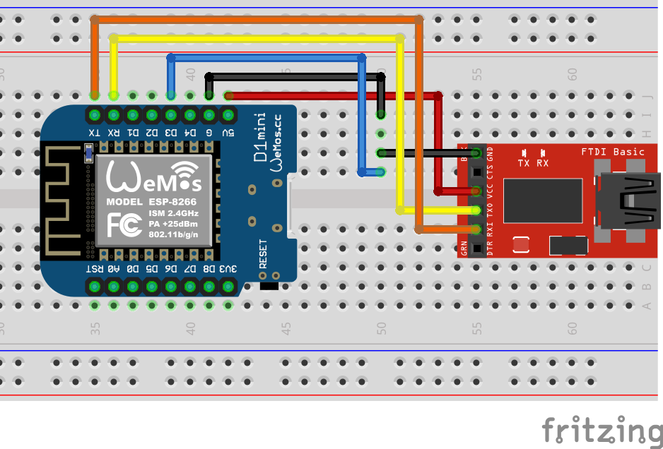
We will then have to go to the programming, this is where we have to take into account several things, the first is that we will not connect the Wemos board through the USB port it incorporates, due to the multiple problems it has for the installation of the Drivers, we will connect the board through a USB-Serial module (FT232RL) for this case, besides that we must also connect a ground pin to enter the programming mode, but first let's explain the connections To make:
Uploading Program to WemosD1mini (ESP8266)As shown in the diagram, the FT232 has a 5V Pin and a GND pin, the ESP8266 module works at 3.3v but the Wemos board already has a voltage regulator incorporated so you only have to connect the 5V to the FT232 to the 5V of the wemos and the same with the grounds, followed by the TX of the FT232 to the RX of the wemos and the RX of the FT232 to the TX of the Wemos, which will already have a serial communication satisfactory.
But to enter programming mode it is necessary to ground the D3 pin, this is only done when you want to program the board, for normal operation you have to remove this ground pin at the start.
Once this procedure is done we can start the normal programming, remember to choose the port where the FT232 is and choose the board we want to work.
The physical connections with jumpers look something like this:
Finished this we already have our Wemos correctly programmed, what remains then is to mount it on the protoboard together with the movement sensor and the module Relay.
If the arduino serial port monitor is opened and the serial communication is configured at 9600 baud and we remove ground from pin D3, by pressing the reset button, we must obtain the following:
This way we check what board is working correctly.
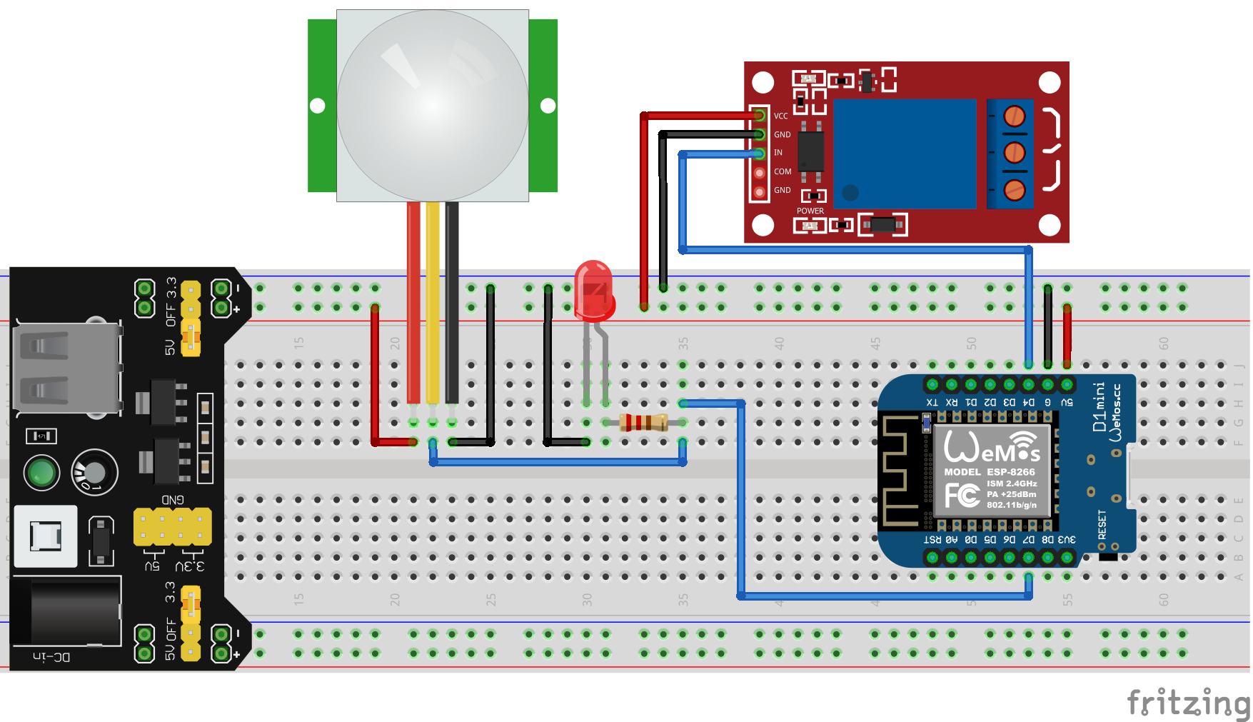
HARDWAREFor the assembly of the hardware we have to take into account what will be the power supply of the whole circuit, I will use a charger for a Smartphone and I will connect it to a voltage regulator for protoboard, from here I will obtain all the voltages necessary for the correct operation of the project.
PIR Sensor:
This motion sensor is very simple, you simply put a 5V supply and the corresponding ground, the module gives us a 1 and a 0 depending on whether or not there is movement, this pin we send to the input pin of the Wemos and there we place an LED with its respective resistance to see the effect of the motion sensor.
Relay Module:
For this case I have a built-in 4 relays but for this application we will only use one, it is simple only connect the power supply which will also be 5V and ground, the respective output of the wemos board must be connected to the input that activates the relay.
The next thing to know is how to connect the light we are going to turn on, for this case as what I want to turn on is the light from a room of my house what I will do is to modify the wall switch that turns on this bulb, What I will do is to connect two cables in parallel and these I will connect in the respective open output of the relay. This connection will provide control over the bulb, but in turn we can also have functional the wall switch. Everything is explained in more detail in the connection diagram:
Finally the complete schematic diagram and its connection in protoboard:
At this point our project is working properly.
Video of operation:
Any comments are welcome.


Comments