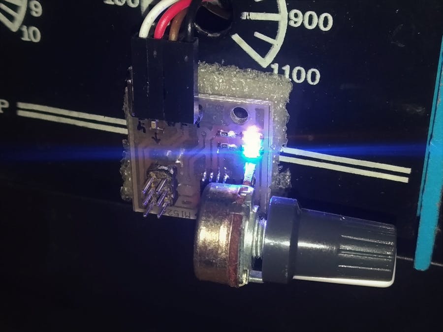
I had a damaged heater laying around, so I decided to make a simple isolated dimmer to control the heat.
We've seen many simple MCU-based dimmers work as follow:
- a zero-cross detection circuit, makes an interrupt on MCU pin
- MCU pulses a triac with a delay which corresponds to desired power delievery
so if we are using a 230V 50Hz line, a zero delay makes triac on as soon as crossing the half-cycle. a 10ms delay makes the triac off all the time. (1s/50Hz = 20ms, 10ms each half-cycle).
any delay between 0ms and 10ms reduces the power delievered and in case of a light bulb, dims the light.
here comes the drawback:the power delievered to the resistive load, is nonlinear with the simple delaying. so a 3ms delay, doesn't mean we have 7/10 of power delieverd to the load. that's why other dimmers change the light a lot when the light is low, but changes at higher light levels are not observable. a non-linear nature I didn't want on my dimmer.
that's because the power is sinosuidal, not linear!
workaround:the deliever linear power to load, we have to make our delay timings the way so the partial intergral of the sinewave remains same between dimming steps.
let's say we need 10 steps of dimming, so we need 10 timings so the partial integrals remain unchanged in value. the total intgral of sine from zero to pi is :
we need 10 portions of it. so :
according to the description of the above formula, we have to divide the range of -1 to +1 into some sections, and calculate the n for each section :
here is some values I calculated for 10 timings :
in the table above, delays should be multiplied by 10ms of a half-cycle lenght. e.g. if we want to deliever 0.3 of power to the load, we have to delay 0.63*10ms = 630 microseconds. without this equations we would delay 0.7 which was not accurate.
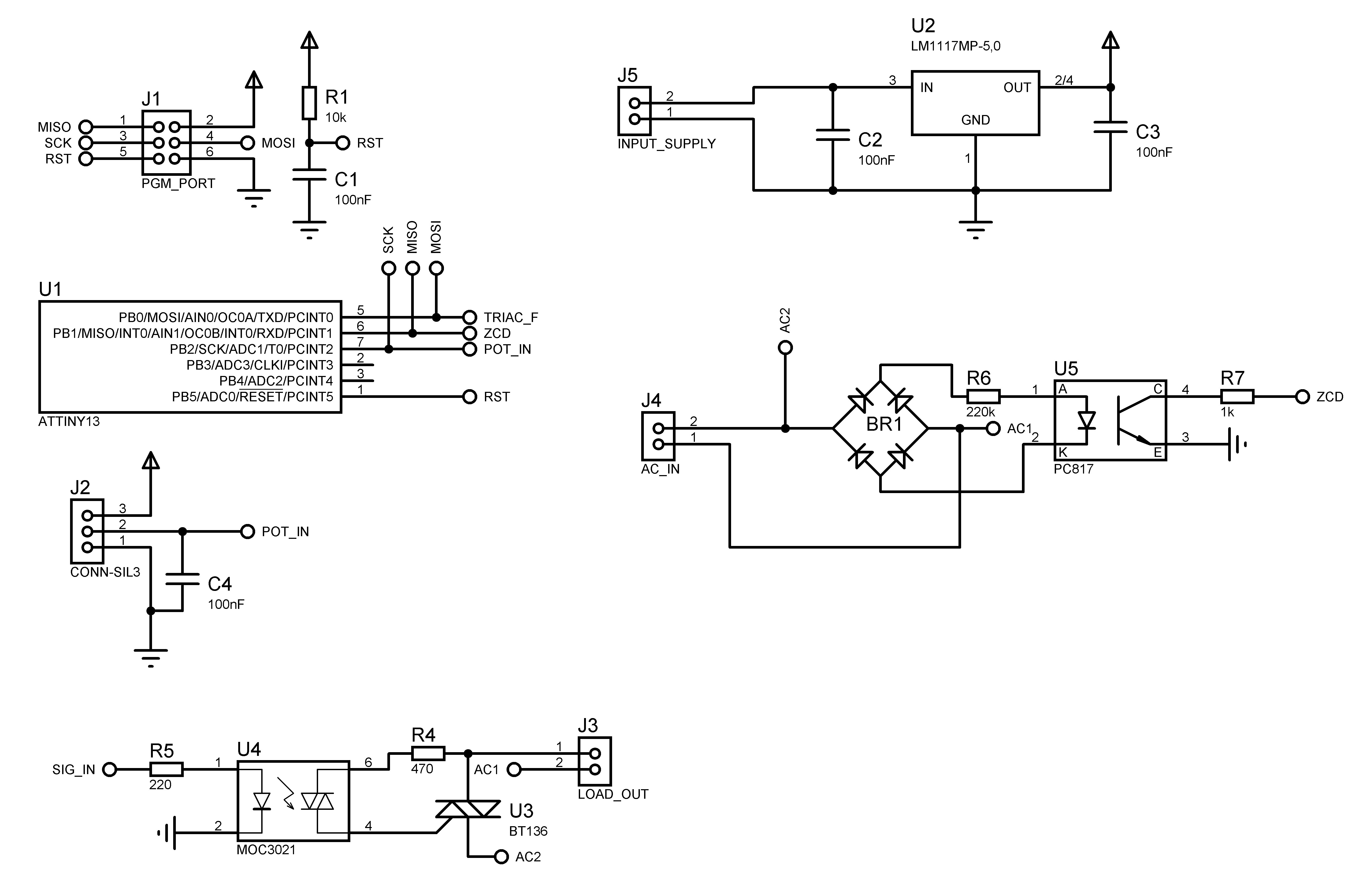
OK, now the circuit :it's as simple as it seems. two LEDs change intensity when going from 0 to 10 dimming levels.


Comments
Please log in or sign up to comment.