


Hardware components | ||||||
_ztBMuBhMHo.jpg?auto=compress%2Cformat&w=48&h=48&fit=fill&bg=ffffff) |
| × | 1 | |||
 |
| × | 1 | |||
 |
| × | 100 | |||
| × | 10 | ||||
 |
| × | 10 | |||
| × | 10 | ||||
 |
| × | 10 | |||
Software apps and online services | ||||||
 |
| |||||
| ||||||
| ||||||
| ||||||
Hand tools and fabrication machines | ||||||
 |
| |||||
 |
| |||||
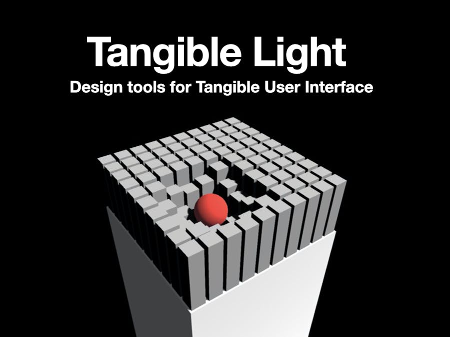
This is a conceptual app platform designed for tangible user interfaces, and we want to make the app easy to use, so even people who don't have deep experience in programming can design, publish their own applications on this software.
On the home page of the software, there are two main sections here. The section above is an online platform just like the App Store on mobile phones, where developers, designers can publish their applications. The other section is the toolsets that you can use them to design applications. It looks like Unity's typography, having many SDK, API, and other stuff embedded in the software. The software itself is connected to the wireless hardware, thus makes it possible to test your application design in real-time through sending matrics of the display signals.
The hardware we used is a simplified version of the well-known tangible user interface from MIT, inFORM. However, the one we built is not licensed from MIT, but our personal built. The main purpose is to present our software ideas. To know more about the original one, please click the link here.
There are software and hardware in this project, and I'll go through the detail in each of them.
Firstly, we use Unity to build a virtual inFORM and various buttons as our user interface, and the data will be sent from the Unity backend to the connected computer as a text file. Next, Processing can read the text file and send the data through the serial port. Finally, Arduino can perform the synchronous operation as the virtual one by reading data on the serial port.
On the other hand, for the hardware, there are three layers in this device:
1. Top Pins: We cut the styrofoam into the cuboid pieces, and glue them with the magnet wire at the end of the linkage.
2. Linkage: The linkage, a magnet wire inside a plastic housing(hollow nylon rods), is used to link each pin with an actuator, thus enable a dense pin arrangement independent of actuator size. Besides, it can transmit bi-directional force from the servo motor.
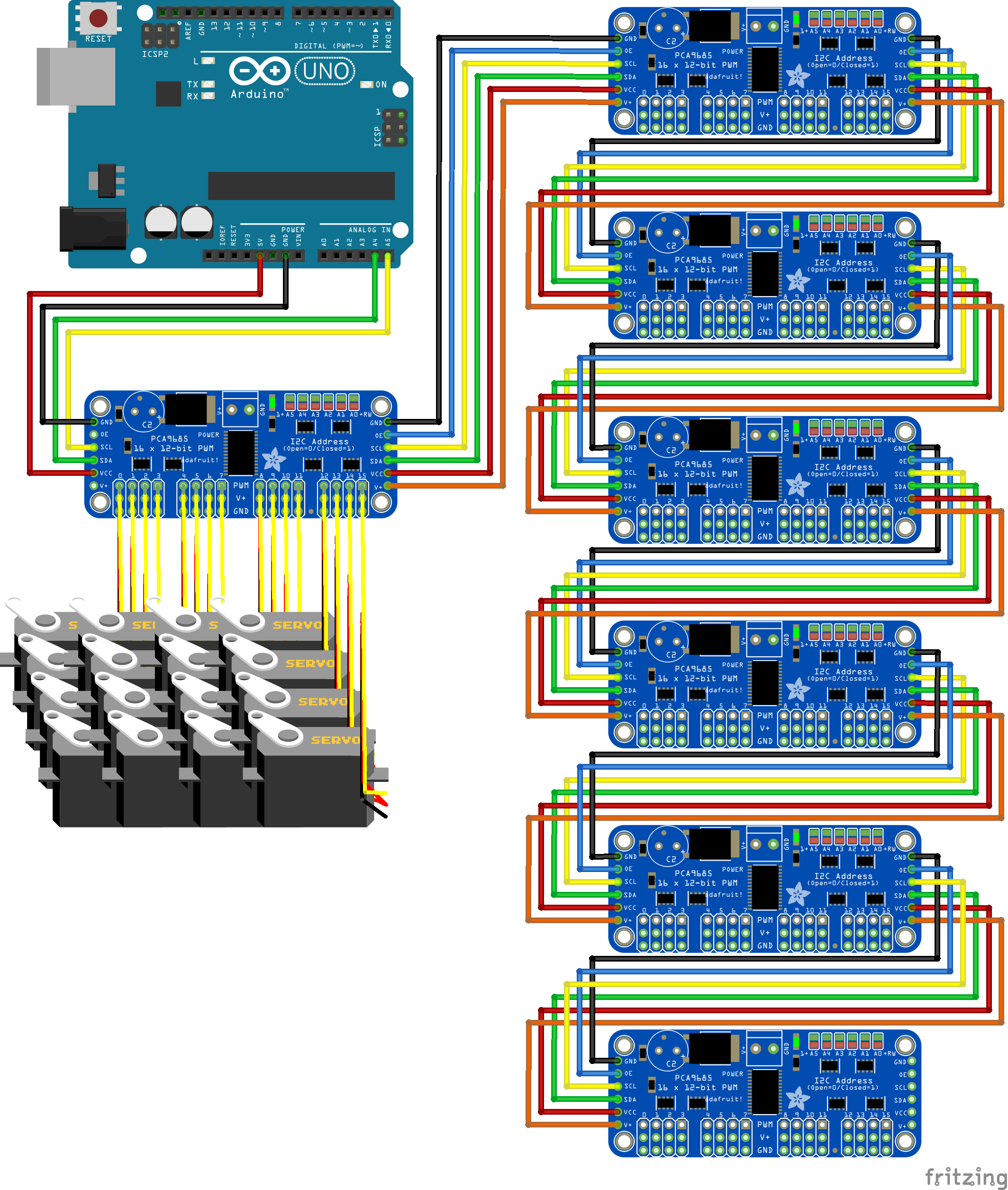
3. Servos Matrix: 100 servo motors are arranged in a matrix form to actuate the linear movement of the pins, and are F through PCA9685 servo drivers.
After the assembly, the device can be controlled by Arduino IDE, and perform specific tests. In this demo, we triggered a sine wave on the first row of the matrix.
Future WorkThe demo shows the fast response and steady movement. However, there are some deficiencies due to our budget and engineering problems, causing the device to lack of further functionality.
1. The power system problem: We had spent so much time fixing the power issue which causes the pins not to move simultaneously. Whenever each row of pins was tested separately, it performs as well as the one in the demo, but not in the case of testing them all together. We are still looking for a solution.
2. The pin constraints problem: The pins are placed in the plastic slots to make sure the movement would always stay in one direction. As a consequence of the loose constraints, the pins sometimes tilted slightly when they extend, while tight constraints would increase friction. Therefore, the preferred solution may be increasing the length of the pins, so the ratio of the exposed portion to the hidden portion will be reduced, leading to less tilting condition.
3. The servo unit structure problem: The structure of the unit is not the optimized version, because the racks are not well constrained and occasionally separated from the gear. The problem would not occur most of the time, but pretty annoying when it happens. We are still looking for a solution.
4. No haptic feedback problem: In the original version of the device, the pins can not only perform visual effects but also haptic feedback. Yet, we don't have enough budget to purchase related instruments, so the functionality we made is not very similar to the original one. After all, our main purpose is not to recreate the hardware but to demonstrate the software idea, so this may not be a big issue.
Thanks for reading! I hope you enjoyed it.


_t9PF3orMPd.png?auto=compress%2Cformat&w=40&h=40&fit=fillmax&bg=fff&dpr=2)


Comments
Please log in or sign up to comment.