


Hardware components | ||||||
 |
| × | 1 | |||
 |
| × | 1 | |||
| × | 1 | ||||
| × | 1 | ||||
| × | 1 | ||||
| × | 1 | ||||
Software apps and online services | ||||||
 |
| |||||
 |
| |||||
The purpose of this guide is get you up and running with an MSP432P401R LaunchPad, the Seeed Studio Grove BoosterPack, and several Grove modules. This is one of the easy ways to get started with electronics, sensors, and programming with TI technology.
LaunchPad is an ecosystem of low-cost, powerful, and easy-to-use microcontroller development kits from Texas Instruments.
Add-on boards called BoosterPacks add functionality to the LaunchPad development kits like Wi-Fi, motor control, sensing, and displays.
Grove modules are low-cost sensors, actuators, and displays from Seeed Studio that let you rapidly prototype. They use a standard cable and plug and connect to the LaunchPad with the Grove BoosterPack.
- TI LaunchPad
To start off the workshop we will load up the out of box demo code from Code Composer Studio Cloud. CCS cloud is a full development environment that you can run directly from your browser (Chrome recommended). In the demo code we will control our on board RGB LED on the MSP432 LaunchPad through a Graphical User Interface (GUI) on the PC. CCS Cloud and CCS Desktop are good options for more serious development and are integrated with many resources and documentation from TI for both the hardware and software.
The objective of this first lab is to introduce you to the resources available on TI cloud tools and also help you install the MSP432 LaunchPad drivers via CCS Cloud. You can also manually install the drivers using the instructions on the Energia website or get the drivers when installing the desktop version of Code Composer Studio.
For compiling your code examples you have a choice to use the open source GCC compiler or the TI CCS Compiler which gives you a bit more optimization.
Instructions
Step 1
Go to dev.ti.com. Click the CCS Cloud box.
Step 2
If you don't have a myTI account already, you can register for one and then sign in. If you do have one, go ahead and sign in and CCS Cloud will load your virtual workspace. Your work will be saved and you can access it whenever you log back in with your TI account. You can also download any of your work to your local machine or upload to GitHub.
Step 3
You should get a work environment to pop up similar to the image below. If so we are doing well.
Step 4
Now we need to get our demo code. We can find demo code in the TI Resource explorer. Resource explorer contains all the released code examples and many other helpful technical resources for all TI embedded processors from microcontrollers to DSPs. Next navigate back to dev.ti.com and click on the Resource Explorer box. You should arrive to a page like this.
Step 5
Search for MSP432 in the search box up top. In the drop down that appears select "MSP-EXP432P401R - Rev 2.x (Red)"
Step 6
Double check your Package Picker is selecting the latest MSP432 SDK. You can click on the package picker in the upper right square icon next to the home icon. Make sure "SimpleLinke MSP432 SDK" is selected on latest and the related plug-ins. Now you know if you'd like to go back to a previous version of the SDK you can use the Package Picker to customize the versioning.
Step 7
Now in the left hand navigation under the "Software" folder click on the following folders.
"SimpleLink MSP432 SDK..." -> "Examples" -> "Development Tools" -> "MSP-EXP432P401R - Rev 2.x" -> "Demos" -> "outofbox_msp432..." -> "no RTOS"-> "CCS Compiler" -> "outofbox_msp432..".
You should see the below screen when navigated properly:
On the right hand side on the top line above "main.c" there is a little cloud icon that says "Import to CCS Cloud" when you hover over it. Click that and it should open the project in your CCS Cloud workspace. As you can see you have many options to use different compilers and to utilize a Real Time Operating System or not.
Step 8
Go back to the CCS Cloud page and make sure you have the "outofbox_msp432p401r_MSP_EXP432P401R_nortos_ccs" project folder selected on the left hand navigation. You can have main.c open in your program window. Now we are going to upload this to our LaunchPad board.
Step 9
Connect your LaunchPad to the PC with the included USB cable.
Step 10
To run our program on the hardware we are going to click the green play button that says "Run" at the top toolbar. CCS Cloud will now help you install a few items needed to communicate with and flash your TI LaunchPad.
Step 11
You may get a Build dialog to pop up or text may pop up in your console as the code compiles. You should see "build finished" pop up and then a dialog box asking to install the browser extension and TI Cloud Agent. Proceed with the installation of both pieces.
Step 12
After installing both pieces, CCS Cloud needs to restart inside the browser. You can click the refresh button and it should reload the page. Make sure that "outofbox_msp432p401r.." is selected in the left hand navigation as it may have changed on the refresh. You can now click run again.
Step 13
If everything went smoothly you should get a new dialog box indicating it's installing target support for MSP432P401R.
Step 14
Next you may get a dialog about error connecting to the target and a firmware upgrade is required. Proceed with the update. Make sure your LaunchPad is connected to the PC via the USB cable otherwise you may get a different error without the option to update the firmware. If you do, you can refresh the page and repeat the step with the LaunchPad connected.
Step 15
If everything went well, now when you click run you should see the code run and flash to the LaunchPad. You can confirm that the code was written in your output console. Your red LED will be blinking.
Step 16
The out of box demo has two parts. The first part is you can change the speed of the blinking by pressing Button 1 (the left button labeled SW1 or P1.1). You can change the color by pressing Button 2 (the right button labeled SW2 or P1.4). The second part of the demo uses the GUI to control the color. To access the GUI go back to Resource Explorer and open the Out of Box Experience GUI folder.
Step 17
With the LaunchPad still connected to the PC, Click the Connect button. Select the default COM port and click open. You will see the color wheel and sliders which you can manipulate to change the color from the PC. You can also change the value for BPM to change the speed of the blink. Cool!
Make sure to close your connection when done, as we need to free up the serial port for later.
Benefits of TI Cloud
Now you have some experience with using the TI cloud tools. You can use these resources in the future if they suit your needs. As you can see there are other code examples available to explore if you want to use the official SDK, TI-RTOS, or TI provided libraries.
You should also check out the SimpleLink Academy training resources. These will teach you how to use SimpleLink microcontrollers and also learn the basics of how to use Real Time Operating Systems on a SimpleLink MCU.
Another nice benefit of starting in cloud and running the example code is you also now have your drivers which will let you code smoothly in Energia IDE as well. You can manually install your board drivers using the Energia website instructions.
Please note that CCS Cloud (and Code Composer Studio Desktop) will let you code Energia programs. Energia coding does not have to be exclusive to the Energia IDE. To code a new Energia sketch in CCS, go to File > New Energia Sketch...
Lab 2 - Installing EnergiaFor this workshop we will use the Energia IDE to write code and program the LaunchPad. Energia is very similar to the Arduino IDE but is written specifically for TI LaunchPad boards.
Before we begin, please ensure you:
- Download the Energia IDE to your local machine at www.energia.nu/download (be sure to chose the correct OS).
- A Windows install guide is located here, and a Mac OS install guide is located here.
- For Windows, download the drivers. Extract the .zip file and run DPInst64.exe.
To make sure Energia is installed properly and that your LaunchPad is working, we will flash a program to the LaunchPad called "Blink" that will just blink an LED.
Lab 3 - Installing Workshop Library1. Go to the Code section at the bottom of this page.
2. Hit the download button to download the workshop library.
3. This should download a file called Getting_Started_Workshop_Library.zip.
4. Open Energia
5. In the toolbar go to Sketch -> Include Library -> Add .ZIP Library...
6. In the window that pops up find and select "Getting_Started_Workshop_Library.zip" which you previously downloaded.
Lab 3 - Setting Up Energia and loading the first programInstructions:
- 1. Plug in your LaunchPad with the supplied USB cable.
- 2. From the Tools menu at the top of the window, select Boards -> MSP432 LaunchPad.
If you don't see it, you may need to go into Boards -> Boards Manager... and download the MSP432 board support package. Grab the latest version and when complete you should now be able to select it from Boards -> MSP432 LaunchPad
- From the Tools menu at the top of the window, select Serial Port, and then pick the serial port associated with your MSP432 Launchpad.
- From the File menu at the top of the window, select Examples -> 01. Basics -> Blink. This will open the blink example program.
Examine the code to see the basic structure of the program.
- All Energia programs have two required functions: setup() and loop(). Setup is run one at startup and then loop runs continuously.
- PinMode is used to set the direction of a GPIO.
- DigitalWrite is used to set the state of a GPIO.
- Delay pauses execution for a given number of milliseconds.
Click the red arrow pointing to the right at the top left of the Energia window. This will compile and upload your program to the board.
After programming completes verify that the red LED is blinking on your LaunchPad.
To take this a step further try:
- Fading the LEDs by changing the calls from digitalWrite to analogWrite.
- Try using the other colored LEDs on the board (RED_LED and GREEN_LED).
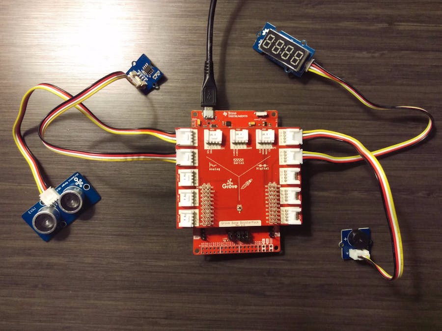
We will be using 4 different Grove modules for this workshop
- Temperature sensor (connected to J6)
- Ultrasonic sensor (connected to J5)
- Buzzer (connected to J13)
- 4 Digit Display (connected to J14)
Now connect the wire between each sensor and the correct port on the booster pack.
Boosterpack to wire connection
Sensor to wire connection
Make sure each sensor is connected to the right port on the Boosterpack as indicated by the arrows below. Finally connect the Boosterpack to the Launchpad. Make sure the orientation matches what you see below. Becareful so no pins are damaged during the process.
Next, we need to install a couple of libraries from Seeed Studio to make the modules work.
Lab 5 - Ultrasonic sensor + 7 Segment DisplayFor this lab, we will use the Ultrasonic ranger and print the measured distance on the 4 Segment display.
In Energia, delete all the code you currently have shown. Then copy the below code and paste it into Energia.
Then click the Upload button in Energia that looks like an arrow pointing to the right.
#include "TM1637.h"
#include "Ultrasonic.h"
/* Macro Define */
#define CLK               39                  /* 4-digital display clock pin */
#define DIO               38                 /* 4-digiral display data pin */
#define BLINK_LED         RED_LED            /* blink led */
#define ULTRASONIC_PIN    23                 /* pin of the Ultrasonic Ranger */
/* Global Varibles */
TM1637 tm1637(CLK, DIO);                  /* 4-digital display object */
Ultrasonic ultrasonic(ULTRASONIC_PIN);    /* Ultrasonic Ranger object */
int distance = 0;                         /* varible to store the distance to obstacles in front */
int blink_interval = 0;                   /* led delay time */
int8_t bits[4] = {0};                     /* array to store the single bits of the value */
/* the setup() method runs once, when the sketch starts */
void setup() {
   /* Initialize 4-digital display */
   tm1637.init();
   tm1637.set(BRIGHT_TYPICAL);
   /* declare the red_led pin as an OUTPUT */
   pinMode(RED_LED, OUTPUT);
}
/* the loop() method runs over and over again */
void loop() {
   distance = ultrasonic.MeasureInCentimeters();   /* read the value from the sensor */
   memset(bits, 0, 4);                             /* reset array when we use it */
   for(int i = 3; i >= 0; i--) {
       /* get single bits of the analog value */
       bits[i] = distance % 10;
       distance = distance / 10;
       tm1637.display(i, bits[i]);                 /* display by 4-digital display */
   }
   delay(100);
}
For this lab, we will use the Temperature Sensor v1.2 and the Buzzer modules to make an alarm that goes off when the temperature gets too high.
In Energia, delete all the code you currently have shown. Then copy the below code and paste it into Energia.
Then click the Upload button in Energia that looks like an arrow pointing to the right.
#include <math.h>
#include "DHT.h"
const int pinTempSensor = 24;     // Grove - Temperature Sensor connect to A5
DHT dht(pinTempSensor, DHT22);            /* temperature&humidity sensor object */
void setup()
{
 Serial.begin(9600);
 dht.begin();                         /* initialize temperature humidity sensor */
 pinMode(40, OUTPUT);
}
void loop()
{
 float temperature = dht.readTemperature(true);
 Serial.print("temperature = ");
 Serial.println(temperature);
 if (temperature > 83) // Sound the alarm if the temp is too high!
   {
     for(int i = 0; i < 10; i++ )
     {
       digitalWrite(40, HIGH);
       delay(10);
       digitalWrite(40, LOW);
       delay(10);
     }
   }
 delay(100);
}
With a buzzer present, of course we have to play some tunes. We will make use of the tone API in Energia.
In Energia, delete all the code you currently have shown. Then copy the below code and paste it into Energia.
Then click the Upload button in Energia that looks like an arrow pointing to the right.
/*
Grove - Birthday Tune
Play birthday tune through the buzzer, demonstrating
buzzer tune() API and pitch/tone (hence music) generation
Dec 2012 - Created for Educational BoosterPack
           buzzer Pin = 19
Dec 2013 - Modified for Educational BoosterPack MK II
           buzzer Pin = 40
Jun 2016 - Modified for Grove Buzzer
           buzzer Pin = 40
by Dung Dang
*/
/*************************************************
* Public Constants
*************************************************/
#define NOTE_B0  31
#define NOTE_C1  33
#define NOTE_CS1 35
#define NOTE_D1  37
#define NOTE_DS1 39
#define NOTE_E1  41
#define NOTE_F1  44
#define NOTE_FS1 46
#define NOTE_G1  49
#define NOTE_GS1 52
#define NOTE_A1  55
#define NOTE_AS1 58
#define NOTE_B1  62
#define NOTE_C2  65
#define NOTE_CS2 69
#define NOTE_D2  73
#define NOTE_DS2 78
#define NOTE_E2  82
#define NOTE_F2  87
#define NOTE_FS2 93
#define NOTE_G2  98
#define NOTE_GS2 104
#define NOTE_A2  110
#define NOTE_AS2 117
#define NOTE_B2  123
#define NOTE_C3  131
#define NOTE_CS3 139
#define NOTE_D3  147
#define NOTE_DS3 156
#define NOTE_E3  165
#define NOTE_F3  175
#define NOTE_FS3 185
#define NOTE_G3  196
#define NOTE_GS3 208
#define NOTE_A3  220
#define NOTE_AS3 233
#define NOTE_B3  247
#define NOTE_C4_1 260
#define NOTE_C4  262
#define NOTE_CS4 277
#define NOTE_D4  294
#define NOTE_DS4 311
#define NOTE_E4  330
#define NOTE_F4  349
#define NOTE_FS4 370
#define NOTE_G4  392
#define NOTE_GS4 415
#define NOTE_A4  440
#define NOTE_AS4 466
#define NOTE_B4  494
#define NOTE_C5  523
#define NOTE_CS5 554
#define NOTE_D5  587
#define NOTE_DS5 622
#define NOTE_E5  659
#define NOTE_F5  698
#define NOTE_FS5 740
#define NOTE_G5  784
#define NOTE_GS5 831
#define NOTE_A5  880
#define NOTE_AS5 932
#define NOTE_B5  988
#define NOTE_C6  1047
#define NOTE_CS6 1109
#define NOTE_D6  1175
#define NOTE_DS6 1245
#define NOTE_E6  1319
#define NOTE_F6  1397
#define NOTE_FS6 1480
#define NOTE_G6  1568
#define NOTE_GS6 1661
#define NOTE_A6  1760
#define NOTE_AS6 1865
#define NOTE_B6  1976
#define NOTE_C7  2093
#define NOTE_CS7 2217
#define NOTE_D7  2349
#define NOTE_DS7 2489
#define NOTE_E7  2637
#define NOTE_F7  2794
#define NOTE_FS7 2960
#define NOTE_G7  3136
#define NOTE_GS7 3322
#define NOTE_A7  3520
#define NOTE_AS7 3729
#define NOTE_B7  3951
#define NOTE_C8  4186
#define NOTE_CS8 4435
#define NOTE_D8  4699
#define NOTE_DS8 4978
int buzzerPin = 40;
// notes in the melody:
int melody[] = {
  NOTE_C4_1,NOTE_C4, NOTE_D4, NOTE_C4,NOTE_F4,NOTE_E4,
  NOTE_C4_1,NOTE_C4,NOTE_D4,NOTE_C4,NOTE_G4,NOTE_F4,
  NOTE_C4_1,NOTE_C4,NOTE_C5,NOTE_A4,NOTE_F4,NOTE_F4, NOTE_E4,NOTE_D4,
  NOTE_AS4,NOTE_AS4,NOTE_A4,NOTE_F4,NOTE_G4,NOTE_F4};
// note durations: 4 = quarter note, 8 = eighth note, etc.:
int noteDurations[] = {
 4, 4, 2, 2,2,1,
 4, 4, 2, 2,2,1,
 4, 4, 2, 2,4,4,2,1,
 4, 4, 2, 2,2,1};
void setup()
{
pinMode(buzzerPin,OUTPUT);
}
void loop()
{
 for (int thisNote = 0; thisNote < 26; thisNote++) {
   // to calculate the note duration, take one second
   // divided by the note type.
   //e.g. quarter note = 1000 / 4, eighth note = 1000/8, etc.
   int noteDuration = 1000/noteDurations[thisNote];
   tone(buzzerPin, melody[thisNote],noteDuration);
   int pauseBetweenNotes = noteDuration + 50;      //delay between pulse
   delay(pauseBetweenNotes);
   noTone(buzzerPin);                // stop the tone playing
 }
 while(1);
}
Now that you have seen how all 4 Grove modules work, combine them all into a single Energia sketch. You could use the 4 Digit Display to print the temperature and the buzzer to make a proximity alarm, or anything else you can think of!
In Energia, delete all the code you currently have shown. Then copy the below code and paste it into Energia.
Then click the Upload button in Energia that looks like an arrow pointing to the right.
#include "TM1637.h"
#include "Ultrasonic.h"
#include "DHT.h"
#include <math.h>
const int B=4275;                 // B value of the thermistor
const int R0 = 100000;            // R0 = 100k
const int pinTempSensor = 24;     // Grove - Temperature Sensor connect to A5
/* Macro Define */
#define CLK               39                  /* 4-digital display clock pin */
#define DIO               38                 /* 4-digiral display data pin */
#define BLINK_LED         RED_LED            /* blink led */
#define ULTRASONIC_PIN    23                 /* pin of the Ultrasonic Ranger */
/* Global Varibles */
TM1637 tm1637(CLK, DIO);                  /* 4-digital display object */
Ultrasonic ultrasonic(ULTRASONIC_PIN);    /* Ultrasonic Ranger object */
DHT dht(pinTempSensor, DHT22);            /* temperature&humidity sensor object */
int distance = 0;                         /* varible to store the distance to obstacles in front */
int blink_interval = 0;                   /* led delay time */
int8_t bits[4] = {0};                     /* array to store the single bits of the value */
/* the setup() method runs once, when the sketch starts */
void setup() {
  Serial.begin(9600);
  dht.begin();                         /* initialize temperature humidity sensor */
  pinMode(40, OUTPUT);
  /* Initialize 4-digital display */
  tm1637.init();
  tm1637.set(BRIGHT_TYPICAL);
  /* declare the red_led pin as an OUTPUT */
  pinMode(RED_LED, OUTPUT);
}
/* the loop() method runs over and over again */
void loop() {
  distance = ultrasonic.MeasureInCentimeters();   /* read the value from the sensor */
  if (distance < 5) // Sound the alarm if the distance is too close!
    {
      for(int i = 0; i < 10; i++ )
      {
        digitalWrite(40, HIGH);
        delay(10);
        digitalWrite(40, LOW);
        delay(10);
      }
    }
  memset(bits, 0, 4);                             /* reset array when we use it */
  for(int i = 3; i >= 0; i--) {
      /* get single bits of the analog value */
      bits[i] = distance % 10;
      distance = distance / 10;
      tm1637.display(i, bits[i]);                 /* display by 4-digital display */
  }
  float temperature = dht.readTemperature(true);
  Serial.print("temperature = ");
  Serial.println(temperature);
  delay(100);
}
In this part of the lab we will utilize GUI Composer. This lab is optional.
- Go back to dev.ti.com and select the GUI Composer icon.
- Log in to your TI account if you have not already and click on the "Getting Started" option. Here you will see resources for learning about the features of GUI Composer. We will go through the prepared tutorial for MSP432.
- Click to the tutorial here in a new tab: https://dev.ti.com/gc/designer/help/Tutorials/monitor/index.html
When finished you can return to this Hackster page to do the next lab.
Lab 10 - Add Bluetooth = IoTThis lab is optional and dependent on available hardware. For this section of the workshop we are going to add some connectivity with Blynk. This demo will be done at the front of the room in most cases. This section is still under development...
ConclusionThat is a good sample of basic prototyping with TI LaunchPad. There is obviously a lot more to do with other Grove modules. There are also many hardware combinations to try. You can learn more about the TI LaunchPad ecosystem at www.ti.com/launchpad and explore the Energia website at www.energia.nu for more ideas and help.


Comments
Please log in or sign up to comment.