


Hardware components | ||||||
_ztBMuBhMHo.jpg?auto=compress%2Cformat&w=48&h=48&fit=fill&bg=ffffff) |
| × | 1 | |||
 |
| × | 1 | |||
| × | 1 | ||||
| × | 1 | ||||
| × | 1 | ||||
| × | 1 | ||||
| × | 1 | ||||
| × | 1 | ||||
| × | 1 | ||||
| × | 1 | ||||
| × | 1 | ||||
 |
| × | 1 | |||
Description
Learning to ride a bike is an important milestone for a child. It’s a major achievements, a moment children and parents never forget. “It’s just like riding a bike,” we say when talking about a skill that becomes a part of you, a skill you have forever.
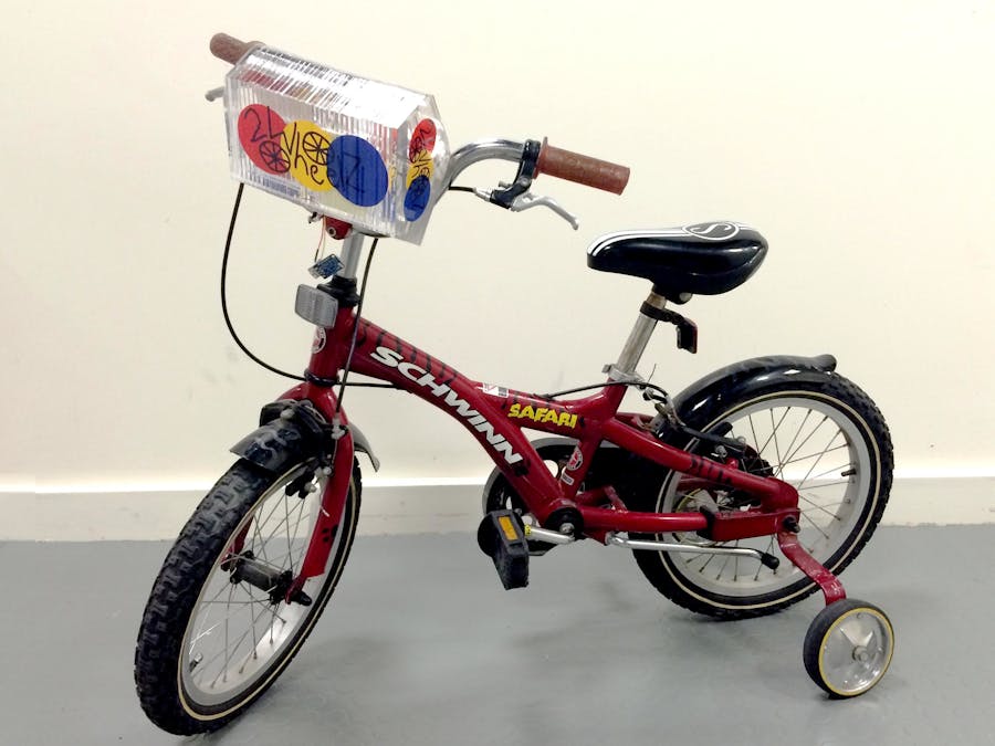
2 Wheelz is a training device for new riders. The self-contained unit is attached on the front handlebars a child’s bike. It’s now tricked out for the learning process.
2 Wheelz contains an accelerometer, an LED strip, and a camera. The accelerometer measures balance while providing visual cues for the LED strip, so the child can learn how to balance in real time. The LED light acts a metronome, but in terms of reflecting the child's real time balance.
As the child leans to one side, the LED light tracks and reflects that movement. By learning to balance, the child will learn to outgrow training wheels. When a child pedals without using the aid of training wheels, a photo is taken. The mounted camera takes a snapshot of the child as they realize they have just learned to ride a bike. This snapshot is than emailed to a pre-programmed list of close family and loved ones, so they can share in this special moment.
Observation
As we were brainstorming modes of human-powered transportation, we wanted to come up with something meaningful, to capture a life experience quintessential to most children. Learning to ride a bike represents a right of passage for many young children. It is something relished and appreciated by friends and family alike.
Many working parents miss out on the experience of their son or daughter riding for the first time. And what is captured always shows the child riding away never the jubilations on the child’s face. We wanted to come up with a way to capture this incredible moment. By incorporating a photo in our attachable handlebar device, we enable this experience to be captured.
The photo benefits not only for the posterity of the child, but for the appreciation of all family members involved. The photo is uploaded to a cloud, and sent to a predetermined email list of grandparents, and loved ones. Enabling all to take part and appreciate the moment in real time.
The LED camera box also provides visual cues that can be an effective tool for children to learn motor skill balance while learning how to ride. We began to examine the different learning styles of children. Recognizing what works well for one child might not work well for another. Through functional studies, we found many participants benefited from the combination of visual and balance inputs. This influenced the scope of our research, focusing on the relationship of visual cues in aiding motor skilled action. We wanted to incorporate a mechanism that could help tie these two relationships together for the benefit of a child learning to ride a bike. We wanted to learn how we could improve the riding experience for the child, while including friends and family in the experience.
Brainstorming
Tracking and Representing Balance
In order to track the balance of the rider we used an adafruit MMA8415 three axis accelerometer, which detected the tilt of the device. The accelerometer came with test code that output acceleration measurements in the X, Y, and Z axes with the Z axis representing gravity. To calculate tilt angle from these values, we took the quotient of the X and Z axis accelerations and calculated the inverse tangent to determine the angle between them.
We determined the tilt angle threshold that would represent when a cyclist was upright and when they were using training wheels or tilting too much. Once we had this threshold, we created a series of Boolean statements that turned on one or two of the LED strip's pixels depending on discrete intervals of the tilt. The pixels corresponded to the angle output of the accelerometer and so we set the middle pixels to zero rotation, the left pixels to negative (counterclockwise rotation) angles, and the right pixels to positive (clockwise rotation) angles.
To add some more visual feedback for the rider, we changed the color of the outermost pixels to orange and red, accordingly. This would provide the rider with feedback that they should lean a different way. A further iteration would be able to turn off and on the led strip to limit the distraction.
Electronics Wiring
The pictures below are quick references on how to wire accerometer, LED strip, and wifi breakout with Arduino. These pictures are taken from Adafruit tutorial website. We use all exactly same pins as in the pictures. Please go through the following tutorials to ensure the proper uses of all the parts. For example, insert a capacitor and a resistor for the LED strip. The libraries of the three components can be found from these links as well.
https://learn.adafruit.com/adafruit-neopixel-uberguide/overview
https://learn.adafruit.com/adafruit-cc3000-wifi/overview
https://learn.adafruit.com/adafruit-mma8451-accelerometer-breakout/overview
We power the Arduino with a battery. Therefore, the LED strip can connect directly to the Arduino 5V pin without additional power source.
Capturing, Saving, and Sending Images
When the bike reaches the threshold for time balanced upright (5 seconds), Arduino will send an HTTP request to inform the server. Our Android app will be communicating with the server every 4 seconds waiting for a signal to take pictures. We program the app to take a picture every 4 seconds for 30 seconds starting from when it receives the message. These images are sent to the server and used for building a slideshow on a webpage. The server also records the date and time at which the pictures are received. The link to the page is then sent to a predefined list of recipients via emails. The overview of the communication between Arduino, the phone, and the server is shown below.
Code
We upload our code on github. The repository consists of four parts in four directories as following.
flask-server
This directory contains code for running a server that communicates with the Arduino and the Android app. This server is built using Flask. In the current setting, this server will serve on port 5000. Make sure that your computer on which you run the server has a static IP address.
First, install flask and uwsgi. On linux, type
pip install flask
apt-get install uwsgi
To run the server in production mode using four threads, type
uwsgi --ini uwsgi.ini
We upload our code on github (see link below). The repository consists of four parts in four directories as following.
To run the server in debug mode, type
python server.py
If your server is working properly, when you browse to 'http://your.server:5000/status' using your browser, you should get “0” back, indicating that camera should be off.
express-server
This directory contains code for running a web server that hosts our webpage. This server is built using Express. In the current setting, this server will serve on port 3030.
First, install node.js express and fs. On linux, type
npm install express
npm
install fs
To run the server, type
node app.js
Now, you should be able to browse to 'http://your.server:3030' using your browser. You should see 2Wheelz webpage without slideshow, since no image has been sent from phone. Once the phone sends images to the Flask server, the Flask server will save the images in ‘public’ directory, and update ‘public/date.txt’ file.
wheelz-arduino
This directory contains the Arduino
code that reads data from accelerometer, controls the LED strips, and
sending a signal to take picture to the server. Don’t forget to change #define WLAN_SSID and #define WLAN_PASS to your valid wifi connection.
Also, change #define WEBSITE “your.server” to URL (Flask server) that
your webpage will be hosted on.
WheelzAndroid
This directory contains the
Android app code that constantly communicates with the server, waits
for the signal, takes pictures, and uploads pictures to the server.
Again, change the URL, which is currently set to “your.server”, to the
server (Flask server) that the app will be communicating with. Most
parts of our program are taken from http://www.41post.com/3794/programming/android-take-a-picture-without-displaying-a-preview.
Packaging the Electronics
For the design our goal was to create a physical object that attached directly to the front of the bike, similar to a basket. The housing can be clipped on and removed from the bike using 3D printed clips. The presentation model, made of acrylic, allows the insides of the device to be visible. The phone is able to be slide in and out of the housing using a removable end plate, and a switch on the bottom allows for 2 Wheelz to be turned off when not in use. There is also USB receiver for charging the Li-Ion battery that powers the entire device including the LED strip.
The acrylic presentation model was generated by contouring the 3D model at .25", which is the thickness of the material, and then laser cut. The pieces were held together with acrylic rods until the final assembly, when those individual pieces were cemented together into two larger units. The two units allow for the parts to be accessible, and when finally assembled, are held together with acrylic rods. The logo was cut out using a vinyl cutter and placed on the inside and outside of the housing.
Attaching and Testing
Next, we 3D-printed custom clips to clip the device onto the bike. (See 3D renderings above). Once 2Wheelz is clicked on the bike, and the phone is inserted into the sleeve, the device is ready to go. To test everything out, we took the bike out for a spin!


Comments
Please log in or sign up to comment.