AboutThisProject
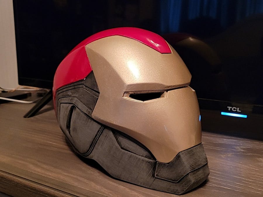
OverviewFor our MEGR 3171 Instrumentation class, we were tasked with creating a project that included the use of two particle argons as well as two different types of sensors and have them work and communicate with each other to achieve a certain goal. For our project, we took a 3-D printed Iron man helmet that had mounted servos that connected to the faceplate allowing us to open and close the helmet at will and LED eyes that we could turn on and off at will.
Since the helmet was able to open and close with the servos we decided to add an ultrasonic sensor to control when the servos would actuate. This would allow us to tell the servos to close the mask if an object came too close to the ultrasonic sensor and open back up if the distance threshold was no longer being met. For the second half of the project, we placed the LED eyes in a circuit with a photoresistor that would sense when the light was no longer hitting the sensor and thus turn the LED eyes on similar to a nightlight by sending in a high signal to the LED.
The two circuits are designed to communicate with each other. The ultrasonic sensor circuit performs a subscribe function that blinks the D7 led on the photoresists whenever the photoresistor circuit performs its publish function every second. The photoresistor circuit can only run when the ultrasonic sensor circuit is running due to running off of a subscribe function that triggers whenever the ultrasonic sensor circuit performs its distance publish event.
DetailsCircuit 1: Ultrasonic Sensor circuit
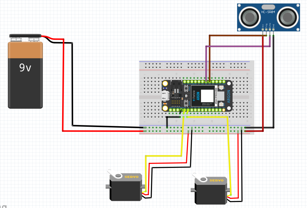
The argon receives power from its usb connection to the laptop while the ultrasonic sensor and both servos receive power from a battery pack. The signal wires (yellow) from the servos are connected to the analog pins of the argon and the echo and trig pins of the ultrasonic sensor are connected to the digital pins of the argon. The argon is grounded to the battery pack.
Circuit 2: Photoresistor circuit
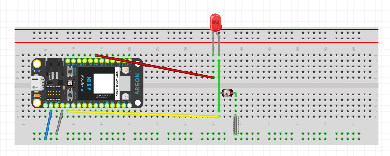
A wire connected the LED to the D6 port on the argon. Another wire gave the circuit power by connecting to the 3v3 port on the argon. A ground wire was connected from the argons ground port. The photoresistor connected to the LED signal in series as well as port A0 from the argon.
Thingspeak ChartsChart showing the distance readout from the ultrasonic sensor, each dip below 20 would close the face plate.
Chart showing the high and low signal outputs from the photoresistor to turn the LED lights on and off, where 1 is a high output and 0 is low output.


_zhWsCcSEcl.jpg?auto=compress%2Cformat&w=48&h=48&fit=fill&bg=ffffff)


Comments
Please log in or sign up to comment.