


Hardware components | ||||||
 |
| × | 1 | |||
| × | 1 | ||||
| × | 1 | ||||
| × | 1 | ||||
| × | 1 | ||||
| × | 1 | ||||
 |
| × | 1 | |||
| × | 1 | ||||
| × | 1 | ||||
| × | 1 | ||||
Software apps and online services | ||||||
| ||||||
 |
| |||||
 |
| |||||
| ||||||
Hand tools and fabrication machines | ||||||
| ||||||
The five of us are Embedded Systems students in Polytech Sorbonne, Paris. This assignment was given to us a few months ago in order to help beekeepers take care of their beehives.
Many problems can happen in a beehive and the beekeeper's job is to help them and cure them whenever he needs to. For example a beekeeper needs to know when there is a hornet waiting at the entrance of the beehive killing every bee coming back from harvesting the precious pollen. Because a hornet can stay stationary and kill as many bees as he like and no beekeeper wants to loose thousands of bees while he's at home taking a break. And hornets aren't rare in this area of France, luckily for us bees emits a specific frequency when scared, this hissing sound is around 3000 Hz, so when a crazy hornet is waiting at their door ready to feast, we can know it ! Using the same method we can know if the bees are swarming or not to capture the old queen escaping and put her in a new beehive, commonly this noise is between 340 Hz and 450 Hz.
The frequency emitted by the bees is not the only data we can get from a beehive, because bees are able to maintain a very stable temperature inside their hive, around 35 degrees Celcius. If their temperature is shifting too much we can tell if they are healthy or not. The weight is also an important data: we can tell the amount of bees and honey inside the beehive ! If the beehive is getting heavier and heavier every day we can give a threshold depending on the size of the beehive for the beekeeper to harvest his honey. And with all this data we can also detect more precisely the swarming.
You may be wondering how are we going to get all of those information, because beehives are often situated in area far from city and in deep countryside, where 4G an option and Wi-Fi is even worse. We'll be using the LPWAN (Low Power Wide Area network) network of Sigfox to increase our autonomy and range, because we won't be transmitting a lot of data, just a few sensor's value, not a live video feed for example. We going to send punctually (every 10min) a short message with all the data compressed to a minimum number of bytes. We had a wide choice of IoT Cloud Platforms, but we chose Ubidots because it was the most intuitive one and the easiest one for beekeepers to use.
For this interesting project we chose one of the most interesting Arduino boards, with incredible capacities and a wide choice of different uses. With its amazing nrf52840 microchip you guessed it we whose the Arduino nano 33 BLE Sense!
It is a simple and effective card both in terms of energy and programming. Indeed we were able to benefit of the public libraries already existing on Arduino for our code, although not always compatible because of the fact that it differs a little from other Arduino. In addition this card contains sensors, such as temperature, humidity, pressure, or Bluetooth low energy. Speaking about Bluetooth low energy we chose to implement it in our project because it is such a cool and handy feature! But as cool as it is, it's a bit tricky and complicated feature to implement, we are going to explain you how it works in our project here:
This protocol have to parts shown below: a client/Central and a server/peripheral.
The Central device will be in every case here the beekeeper's phone so he can get every sensor values live from his hive!
We start by creating Services and Characteristics as global variables so we can use them globally. A service is a group of sensors and values so we can find them easily which are called using randomly created UUIDs. Within each service we can find some Characteristics which represents only one sensor/value.
In our prototype we only have 2 Services, the device info service to specify informations about the hardware used for the hive such as the name, credits and stuff. The second Service is the sensors informations which contains every sensor value we need! You can see below how we implemented our Services and Characteristics!
BLEService optiService("181A");
BLEByteCharacteristic optiStatusCharacteristic(OPTI_CHARACTERISTIC_UUID, BLERead | BLEWrite);
BLEStringCharacteristic tmpCouvCharacteristic(TMP_COUVAIN_CHARACTERISTIC_UUID, BLERead, 20);
BLEStringCharacteristic tmp1Characteristic(TMP_1_CHARACTERISTIC_UUID, BLERead, 20);
BLEStringCharacteristic tmp2Characteristic(TMP_2_CHARACTERISTIC_UUID, BLERead, 20);
BLEStringCharacteristic batCharacteristic(BAT_CHARACTERISTIC_UUID, BLERead, 20);
BLEStringCharacteristic humCouvCharacteristic(HUM_COUVAIN_CHARACTERISTIC_UUID, BLERead, 20);
BLEStringCharacteristic humAmbCharacteristic(HUM_AMBIANT_CHARACTERISTIC_UUID, BLERead, 20);
BLEStringCharacteristic pressionCharacteristic(PRESSION_CHARACTERISTIC_UUID, BLERead, 20);
BLEStringCharacteristic poidsCharacteristic(POIDS_CHARACTERISTIC_UUID, BLERead, 20);
BLEStringCharacteristic freqCharacteristic(Freq_CHARACTERISTIC_UUID, BLERead, 20);
We chose to use BLEStringCharacteristic for most of them because we want to have to the name of the sensor shown below in the data sent. We used LightBlue app on iOS to read the value from the sensor. It works perfectly fine and very easy to use.
As you can see the choice of sending a string was a very wise thing to do if we don't want to have to learn every UUIDs!
This result is obtained by having this initialization:
- Begin BLE and set local name
- Add every Characteristics to a Service
- Add the service to the to BLE
- Set values
- Advertise!
Then when we are advertising we just need to update our values periodically!
This BLE feature is handy to check sensors value without going on internet but mostly necessary if we want to change the delay between 2 measures (to save energy). If you need more informations about BLE feel free to check the official Arduino documentation!
Now we will have a look on our sensors, starting by the weight sensor!
The beehive will be supported on top, the way it works is the following:
To convert those signals into readable values by our microcontroler we will be using a Grove HX711 module made by Seeed and a library made by several contributors on github.
Here is the code we use to interact with our scale.
#include <HX711.h>

HX711 scale;

float Offset = 1936859.00; // Offset pour 66kg

void init_HX711(){
  scale.begin(D6, D5);      // LOADCELL_DOUT_PIN = D7, LOADCELL_SCK_PIN = D6;
  scale.set_scale(Offset);
}

void get_weight(data *data_weight){ //We take as a param a struct with our data
  scale.power_up();
  delay(3000); // We wait a bit for the scale to initialize
  if(scale.wait_ready_retry(3, 500)){
    data_weight->Poids = scale.get_units(5);
    data_weight->Poids = data_weight->Poids * 10;
  }
  if(data_weight->Poids < 0){
    data_weight->Poids = 0;
  }
  scale.power_down();    // We shutdown the scale to save energy
}
We can now have a look at our temperature probes. We chose DS18B20 temperature probes to fit inside the beehive which is shown below:
Those sensors are using the OneWire protocol, which means that they only need one wire to communicate their data. And if we only use one sensor it only need 2 wires total: (VCC + Data) and GND instead of VCC, Data and GND. As handy as this protocol is unfortunatly it isn't implemented on our Arduino 33 BLE Sense because as explained before our microcontroler is not the common Arduino Atmel microcontroler, it uses Mbed so not every library is compatible with it. Luckily we found someone who made a new library for our board! Here is the code we are using to get the temperature from 2 probes in series:
#include <MaximWire.h>

MaximWire::Bus bus(PIN_BUS);
MaximWire::DS18B20 device;

void get_DS18B20(data *data_tempCote){
  unsigned short nbr_sensors;
  float temp;

  for(int i=0; i<2; i++){
    nbr_sensors = 1;
    MaximWire::Discovery discovery = bus.Discover();
    do{
      if (nbr_sensors > 2){
        break;
      }
      MaximWire::Address address;
      if (discovery.FindNextDevice(address)){
          if (address.GetModelCode() == MaximWire::DS18B20::MODEL_CODE){
            MaximWire::DS18B20 device(address);
            temp = device.GetTemperature<float>(bus);
            data_tempCote->Temp_cote[nbr_sensors - 1] = temp;
            device.Update(bus);
          }
      nbr_sensors++; //Increase the sensor counter
      }
    } while (discovery.HaveMore());
  }
}
To get the level of brightness we used an LDR04 photo-resistor. Subsequently we made a voltage divider bridge in order to have a stable value for our photo-resistor. Moreover we tested different values with a lux-meter in order to find a function which would give us the right luminosity according to the voltage change.
The code to get the luminosity:
for(int i=0; i<10; i++){    // average on 10 test
    Vin = analogRead(A7);   // between 0 to 1023
    Vin = Vin * (3.3/1023.0);
    R0 = (R1*3.3/Vin) - R1;
    temp = 500/(R0/1000);
    Lumen += temp;
}
// we get the value in Lumen
For humidity and temperature inside the hive, we use the DHT22 sensor. The DHT22 (or AM2302) communicates with a micro-controller through a serial port, so with a library it is relatively easy to use.
The code to use the DHT22:
void get_DHT22(data *data_DHT){
    data_DHT->Temp_couvain = dht.readTemperature();
    data_DHT->Humi_couvain = dht.readHumidity();
}
Well now that we have seen all our sensors let's take a look on our micro-controller.
All of this need power and we get that through solar energy. We use a solar panel combined with a battery.
We use a Seeed LiPo Rider Pro which is able to store the energy got from the solar panel in the battery we shown before. It was also very handy in while testing because we can power our board using USB and shows the amount of battery left with a 4 LEDs.
The thing with the battery we chose is that as cheap as it is, it is not very efficient so we have to save as much power as we can. To do that we won't be using the LiPo Rider's 5V it can provides because we have a 3.3V powered board which need to have a voltage regulator (already inboard) to convert 5V to 3.3V which uses a lot of power.
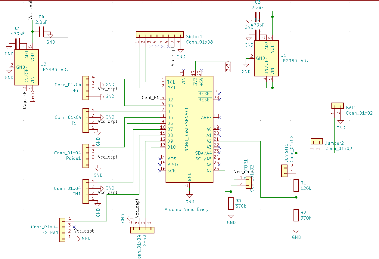
Instead we'll be using a voltage regular who nearly draws no current at all and provides stable 3.3V too, additionally we can turn it off. Being able to turn the 3v3 down is very handy to power the sensors, this way we will have 2 voltage regulators, one which is always on to power the board and one which can be disabled to shutdown sensors so they don't draw current while we don't use them (because we only take one value each 10 mins per sensor).
And finally the most important the Sigfox module which allows us to send values with radio waves.
To make every component work together we printed a PCB (in the description of the project) using our own PCB maker machine.
Once everything was assembled, we made the cables and the box water proof. We also built a sheath for the battery to protect it. Everything is fixed to be resistant to the handling of the beekeeper, to the wind, and to the rain.We have added a switch to make it easier to turn the device off and on.
To protect a maximum our device we added some "potit pieds". It preserve it for being in the mud the rainy days.
To get the value from Sigfox to Ubidot we used Sigfox's backend, choosing wisely our callbacks we were able to send enough data for every sensor we had. Once on Ubidot we decrypt the values which have been compressed to be send as a 32 byte message. And we get all the value in beautiful graphics, with a simple interface.


Comments
Please log in or sign up to comment.