

Hardware components | ||||||
 |
| × | 1 | |||
Software apps and online services | ||||||
| ||||||
 |
| |||||
The article is being published in collaboration with JLCPCB. It is one of the most experienced PCB manufacturers with more than a decade in the field of PCB prototype and fabrication, they are committed to meeting the needs of their customers from different industries in terms of quality, delivery, cost-effectiveness and any other demanding requests.
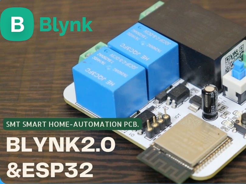
IntroductionIn this article we are going to make a home-automation project using new blynk2.0. and my 2 Node SMT Smart home-automation PCB.
In this home automation project we can control our home-appliances via BLYNK smartphone application, BLYNK web-dashboard from anywhere in this world.
and also we can control our home-appliances via manual switch buttons and we can also monitor the real time status in the BLYNK app.
In the article I will explain circuitry, code and how to setup BLYNK dashboard, So I'll recommend to you, read the entire article till the end.
Apart from 2 node home-automation PCBs, 4 node and 8 node PCBs are also available, these PCBs are fully tested and work very well in automating the devices,
You can install these PCBs in your office, house to make your dump devices smart.
This home-automation PCB is very small in size and compact which can easily fits in your electrical switch boards.
This PCB is compatible for all the smart speakers available in the market like Amazons Alexa, google home and Apples SIRI.
Designing the PCB.To design the circuit and PCB, we used EasyEDA which is a browser based software to design PCBs.
Designing the circuit works like in any other circuit software tool, you place some components and you wire them together.
Then, you assign each component to a footprint.
Having the parts assigned, place each component. When you’re happy with the layout, make all the connections and route your PCB.
Save your project and export the Gerber files.
Ordering the PCBs at JLCPCB.This project is sponsored by JLCPCB. JLCPCB is a full feature Printed Circuit Board manufacturing service.
Turn your DIY breadboard circuits into professional PCBs– get 10 boards for approximately $5 + shipping (which will vary depending on your country).
Once you have your Gerber files, you can order the PCB. Follow the next steps.
1. Download the Gerber files –click here to download the.zip file.
2. Go to JLCPCB website and Click on Quote Now button.
3.Upload the GERBER file you downloaded in the last step. Upload the.zip file or you can also drag and drop the GERBER files.
After uploading the zip file, you’ll see a success message at the bottom if the file is successfully uploaded. You can review the PCB in the Gerber viewer to make sure everything is good.
jlcpcb can grab all the PCB details and automatically fills them for you.
To place the order, click on “SAVE TO CART” button.
Now select the shipping method, the one you prefer and has cost efficient.
Before finalizing your order you can use the promotional code JLC-REBE to get a discount and then click pay.
Now grab all the components whose list is mention below, and soldered on the PCB.
1.ESP32 Chip.
2.Highlink (HLK-5M05).
3.Relay (5volts).
4.Terminal connectors.
5.Optocoupler(PC817).
6.DPDT Switch.
After soldiering rest of components PCB look like this neat, clean and well arranged.
BLYNK 2.0 WEB-DASHBOARD CONFIGURATION.First of all you have to signup on this page using your email id.
Now you have to create a template for your project, to create the template click on the dotted icon as pointed in the image below.
Give the name of your template on which your project is, I am giving it 2 node home-automation.
then select the hardware type in my case it is esp32, and connection type is WIFI..... after that click on done button, and you have successfully create the template for your project.
Now click on data streams then new data-streams select virtual pin, you have to give the name of data-streams, give any conventional name you want.
Select the pin on which you want to control your relay, I am selecting virtual pin V0, & select datatype as Integer.
In the same way create one more data stream as we need to control two relays in our project.
Now go to web dashboard to configure the web-dashboard.
As we need to control two devices so we need two switches....for this drag and drop four switches from widget box one by one.
Click on the setting icon to setup the switch widget for web dashboard.
Give any name for this switch widget, select the data stream for this switch widget. and enable the show on/off labels, after that click on save button.
In similar way configure the second switch widget.
After successfully setup both the switch widget for web dashboard, click on the save button to save all these things.
BLYNK 2.0 MOBILE DASHBOARD CONFIGURATION.After configuring web dashboard we need to configure the mobile dashboard as we want to control the appliances from the smartphone application.
So we need to download the smartphone application, which is available for both iOS as well as for android.
Download new BLYNK IOT application in your smartphone.
Now login through the same email id and passwords that we used in web-dashboard.
Now tap on developer mode, here you get the same project template that we created on the web-dashboard, now we need to setup mobile dashboard for this template.
Open this project and tap on plus icon on the right top corner, a widget box is open, add two buttons one by one.
Now tap on first button, give it any display name for this button, I am giving it button1.
Select the data-stream V1 and mode as a switch that it.
In same way setup both the buttons.
CODEDownload the code and open in the Arduino ide.
First of all you need to add esp32 boards in your Arduino ide if you don't have, if you already have then well and good.
Before you upload the code you need to add two more libraries in your Arduino ide i.e. BLYNK & ACE BUTTON library.
To add these libraries in your Arduino ide, go to tools and click on manage libraries, a popup will came, here you have to type blynk, select latest version and click on install
After successfully installation of this BLYNK library, type and search ACEBUTTON library again, select latest version and click on install....it will take few seconds to install the library.
after successfully libraries installation, close this window.
We need to add BLYNK template ID and BLYNK device name, which we will get from the info section of BLYNK dashboard.
Just copy these two lines and paste in the code.
Rest of the code is okay no need to change the code if are using my PCB.
Now select right board and com port and hit upload button.
To upload code in the home-automation PCB, we will use esp32 development board.
Connect the home-automation PCB to the esp32 development board as shown in the schematic above.
While uploading the code press and hold boot button in the home-automation PCB and press once reset button to make PCB go inside boot mode.
WIFI Credentials Over the air.
Now we have to add the WIFI credentials, for this we don't need to hardcode the credentials as we traditional do, we can easily update it via blynk application over the air.
Tap on add new device then click on connect to Wi-Fi.
Your phone will connect to the esp32 via Wi-Fi, tap to join the Wi-Fi.
Now select Wi-Fi network on which you want to run your home-automation system.
Enter the password of your Wi-Fi. then tap on continue, It will takes few seconds to join esp32 to your Wi-Fi.
Here our blynk home-automation project is ready to use.
Make the connections of all the bulb and switches as per schematic shown below.
Thankyou so much for reading.


Comments