


_Owo51ooXAa.png?auto=compress%2Cformat&w=40&h=40&fit=min&dpr=2)

Hardware components | ||||||
 |
| × | 1 | |||
 |
| × | 1 | |||
 |
| × | 1 | |||
 |
| × | 1 | |||
 |
| × | 1 | |||
Software apps and online services | ||||||
 |
| |||||
 |
| |||||
At present, common NFC wireless card readers in the market are based on WiFi or Bluetooth, with high power consumption and limited wireless transmission distance. LoRaWAN® is characterized by long transmission distance, low reception sensitivity and low power consumption.
Therefore, the use of LoRaWAN® can make up for the shortcomings of the above two wireless devices. The data transmission volume of NFC is also relatively small, which is very suitable for LoRaWAN® transmission mode. The card reader with LoRaWAN® wireless transmission is easy to install and deploy. It is battery powered, and can be used for more than half a year.
The main idea of this project is to build a wireless card reader that supports LoRaWAN® through WisBlock. When the card reader reads the electronic tag data, the electronic tag information will be automatically uploaded to the LoRaWAN® built-in server of RAK7268 WisGate Edge Lite 2.
The Hardware usedThe main hardware of this project uses WisBlock kit. The MCU selects RAK4631 WisBlock Core module, which adopts the Nordic nRF52840 MCU, supports Bluetooth 5.0 (Bluetooth low energy consumption) and the latest LoRa® transceiver SX1262 from Semtech company. It supports LoRa® and Bluetooth communication modes.
NFC selects the RAK13600 NFC card reader module of the WisBlock Ecosystem, which uses a PN532 chip and supports the reading and writing of ISO/ICE 14443A/B card type.
It is also equipped with a buzzer module RAK18001, which provides a buzzer reminder when NFC card swiping is valid.
The software of this project uses the RUI3 development platform. RUI3 provides WisBlock with a lot of API interface functions, including sensor driver interfaces and wireless transmission interfaces. There is only a need to write a small amount of application code to complete this product development.
Step 1 - Hardware circuit constructionHardware preparation:
- Nordic nRF52840 BLE Core Module for LoRaWAN with LoRa SX1262 | RAK4631 / RAK4631-R
- WisBlock Base Board | RAK5005-O
- NFC RFID NXP PN532 | RAK13600
- Buzzer Module Jiangsu MLT-5020 | RAK18001
- Two ISO/ICE 14443A/B cards
- Unify Enclosure IP65 100x75x38mm
- 3dBi SubG Antenna | (Antenna for LoRa®)
- 5 M2.5x4 Screws And 8 M1.2x3 screws
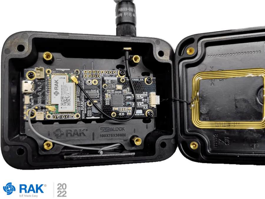
Hardware assembly:
Fasten the RAK4631 module to the position of the CPU SLOT, the RAK13600 to the position of the IO SLOT, and the RAK18001 to the SLOT A (or SLOT B), and use the fixing screws to fix the module.
Connect the NFC antenna, LoRa® antenna, Bluetooth antenna, and install them into the enclosure.
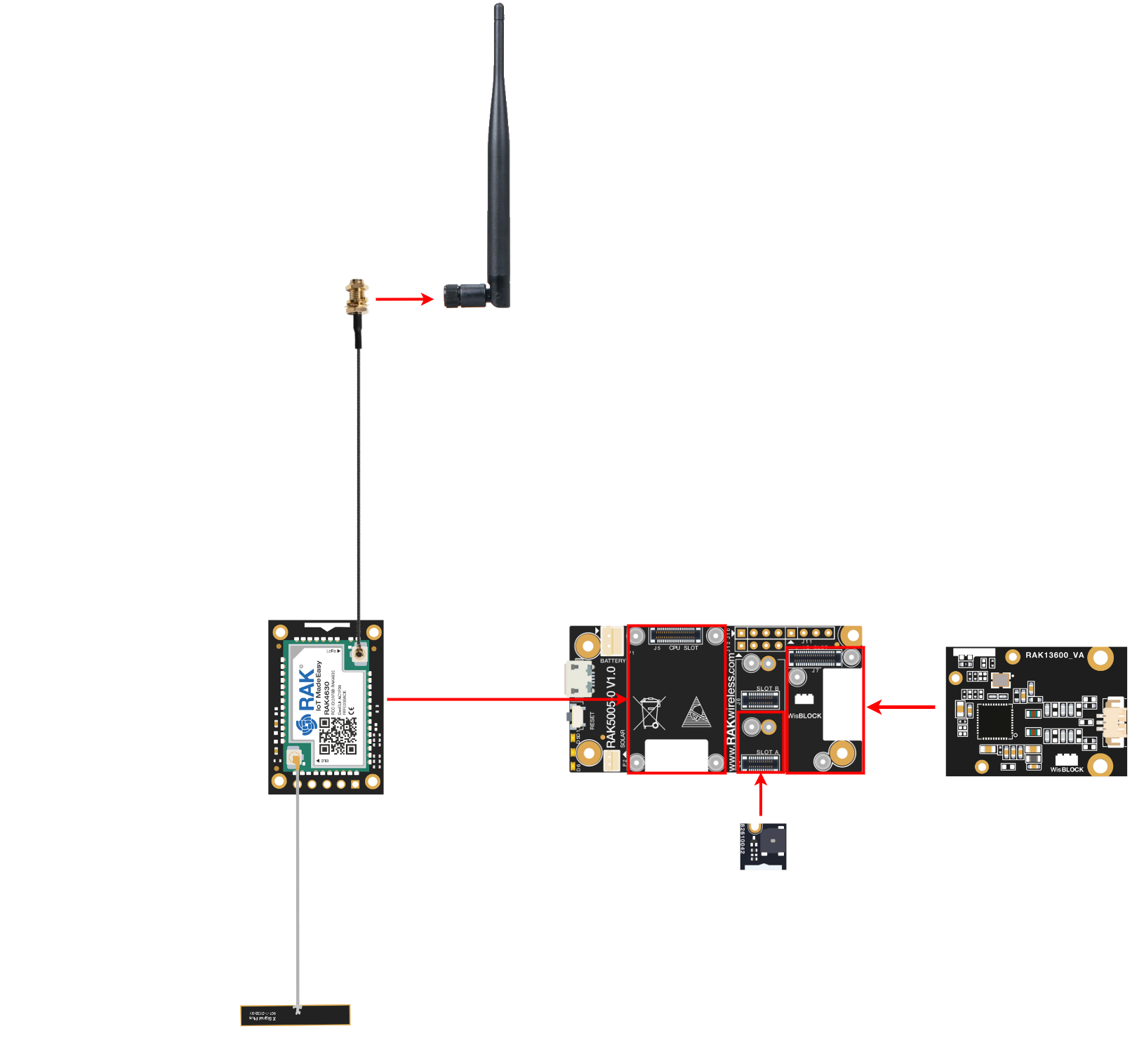
Here is the schematic to guide you in the process of assembly
Add RAK4631-R development board in Arduino IDE:
- Open Arduino IDE and go to File > Preferences.
- To add the RAK4631-R WisBlock Core to your Arduino Boards list, you need to edit the Additional Board Manager URLs. Click the icon.
- Copy the URL
https://raw.githubusercontent.com/RAKWireless/RAKwireless-Arduino-BSP-Index/main/package_rakwireless.com_rui_index.jsonand paste it on the field. If there are other URLs already there, just add them on the next line. After adding the URL, click OK.
- Restart the Arduino IDE.
- Open the Boards Manager from Tools Menu.
- Write
RAKin the search bar. This will show the available RAKwireless WisBlock Core boards that you can add to your Arduino Board list. Select and install the RAKwireless RUI nRF Boards
- Once the BSP is installed, select Tools > Boards Manager > RAKWireless RUI nRF Modules > WisBlock Core RAK4631 Board.
Install the RAK13600-PN532 library and the Adafruit bus library:
Initialization of LoRaWAN® part. This function initializes all parameters of the protocol stack. The network access method is OTAA. Users need to modify this macro definition according to their frequency band and network access parameters. The frequency band used in the code is AS923.The NFC chip initialization code adopts the IIC communication protocol. After the initialization is completed, the card swiping function of NFC can be used.
/*************************************

   LoRaWAN band setting:
     RAK_REGION_EU433
     RAK_REGION_CN470
     RAK_REGION_RU864
     RAK_REGION_IN865
     RAK_REGION_EU868
     RAK_REGION_US915
     RAK_REGION_AU915
     RAK_REGION_KR920
     RAK_REGION_AS923

 *************************************/
#define OTAA_BAND     (RAK_REGION_AS923)
#define OTAA_DEVEUI   {0x11, 0x22, 0x33, 0x44, 0x55, 0x66, 0x77, 0x88}
#define OTAA_APPEUI   {0x11, 0x22, 0x33, 0x44, 0x55, 0x66, 0x77, 0x88}
#define OTAA_APPKEY   {0x11, 0x22, 0x33, 0x44, 0x55, 0x66, 0x77, 0x88, 0x11, 0x22, 0x33, 0x44, 0x55, 0x66, 0x77, 0x88}

void lora_init()
The buzzer is controlled by PWM. When the buzzer is not in use, the output needs to be turned off.
pinMode(BUZZER_CONTROL,OUTPUT);
 noTone(BUZZER_CONTROL);
The NFC chip initialization code adopts the IIC communication protocol. After the initialization is completed, the card swiping function of NFC can be used.
nfc.begin();
  uint32_t versiondata = nfc.getFirmwareVersion();
  if (! versiondata) {
    Serial.print("Didn't find PN53x board");
    while (1); // halt
  }

  // Got ok data, print it out!
  Serial.print("Found chip PN5"); Serial.println((versiondata >> 24) & 0xFF, HEX);
  Serial.print("Firmware ver. "); Serial.print((versiondata >> 16) & 0xFF, DEC);
  Serial.print('.'); Serial.println((versiondata >> 8) & 0xFF, DEC);
  // Set the max number of retry attempts to read from a card
  // This prevents us from waiting forever for a card, which is
  // the default behaviour of the PN532.
  nfc.setPassiveActivationRetries(0xFF);

  //configure board to read RFID tags
  nfc.SAMConfig();

  Serial.println("Waiting for an ISO14443A card");
Cycle to read whether there is an NFC card every 1s. If the ID is read successfully, the buzzer rings for 150ms, and then sends the card ID to the LoRaWAN® server.
void loop(void) {
  boolean success;
  uint8_t uid[] = { 0, 0, 0, 0, 0, 0, 0 };	// Buffer to store the returned UID
  uint8_t uidLength;				// Length of the UID (4 or 7 bytes dep        ending on ISO14443A card type)

  // Wait for an ISO14443B type cards (Mifare, etc.).  When one is found
  // 'uid' will be populated with the UID, and uidLength will indicate
  // if the uid is 4 bytes (Mifare Classic) or 7 bytes (Mifare Ultralight)
  success = nfc.readPassiveTargetID(PN532_MIFARE_ISO14443A, &uid[0], &uidLength);

  if (success) {
    tone(BUZZER_CONTROL,4000);
    delay(150);
    noTone(BUZZER_CONTROL);
    Serial.println("Found a card!");
    Serial.print("UID Length: "); Serial.print(uidLength, DEC); Serial.println(" byte       s");
    Serial.print("UID Value: ");
    for (uint8_t i = 0; i < uidLength; i++)
    {
      Serial.print(" 0x"); Serial.print(uid[i], HEX);
    }
    Serial.println("");

   digitalWrite(ledPin1, HIGH); // LED turn on when input pin value is HIGH
   delay(150);
   digitalWrite(ledPin1, LOW); //

  /** Send the data package */
  if (api.lorawan.send(uidLength, (uint8_t *) & uid, 2, true, 1))
  {
    Serial.println("Sending is requested");
  }
  else
  {
    Serial.println("Sending failed");
  }

    // Wait 1 second before continuing
    delay(1000);
  }
  else
  {
    // PN532 probably timed out waiting for a card
    Serial.println("Timed out waiting for a card");
  }
}View the real-time serial port log through WisToolBox
With the RAK7268 built-in LoRaWAN®, there is also a server log if you need to confirm if the data has been successfully sent.
After successfully building your NFC card reader with LoRaWAN connectivity you have several options to implement it in multiple scenarios such as merchandise control through Tags, user entry control, building security control among many other things, and remember as we always say #IoTMadeEasy.
Also, follow us on our Hackster Hub and be part of our community to keep updated with more DIY IoT projects and news.
If you want to buy our products please visit our store
Please share with us, write about your doubts and interact with us in the comment section.
_Owo51ooXAa.png?auto=compress%2Cformat&w=60&h=60&fit=min&dpr=2)


_M6kErcYJ84.png?auto=compress%2Cformat&w=40&h=40&fit=fillmax&bg=fff&dpr=2)
Comments
Please log in or sign up to comment.