


Hardware components | ||||||
 |
| × | 4 | |||
 |
| × | 4 | |||
 |
| × | 4 | |||
 |
| × | 1 | |||
 |
| × | 4 | |||
| × | 1 | ||||
 |
| × | 1 | |||
Software apps and online services | ||||||
| ||||||
Hand tools and fabrication machines | ||||||
 |
| |||||
Our local Hackster Live chapter met in May 2017 to learn all about PCBs and using Upverter to capture, layout and design a PCB. I gave a brief presentation about the basic elements of a PCB before moving onto using Upverter. Using a seriesofprojects published by the wonderful Monica Houston and Katie Kristoff as a guide, we started working on capturing a schematic and laying out a PCB based off the Simon Says arduino shield. After our meetup, I finished our schematic/layout, and used Seeed Studio's Fusion PCB service to have our shield PCB manufactured and ordered the components for the board from Newark. Finally, once we received the bare PCBs and components, we met up and a brief assembly/soldering meetup.
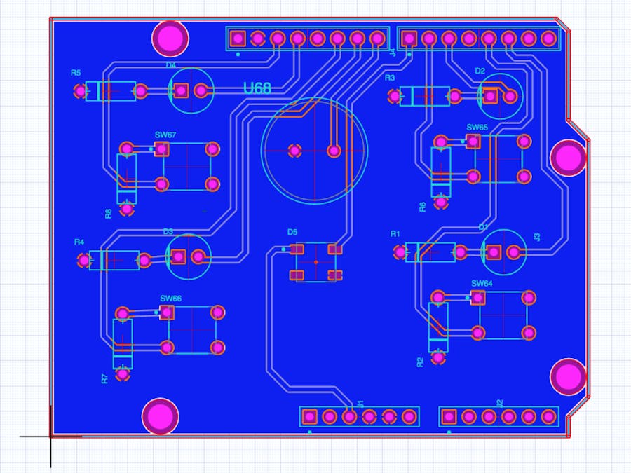
Designing the PCBAs mentioned above, we based our project off of the guide that Monica and Katie posted. This project is a good place to start for people who've never designed a PCB before and gave us a good opportunity to discuss the various components that make up these essential parts of our projects. Additionally, we were able to learn and introduce members to Upverter, a cloud based PCB design tool.
The shield itself isn't too complicated to generate a schematic and layout for. We added a WS2812b addressable RGB LED to customize it a little bit (and give a little more feedback for the game) and we chose slightly different components for the pushbuttons and piezo buzzer based on what was available from Newark. Next steps were to get the boards made and parts ordered!
Getting the PCB ManufacturedUpverter allows you to easily generate Gerbers for manufacturing. On the bottom of the project page are options for exporting the design to various formats. For Seeed Studio's Fusion service, we need to export the RS-274X Gerbers. Clicking the highlighted link will download a.zip archive containing the various gerber files.
Once you have the.zip file, you'll have to extract the files. Fusion PCB expects drill files to end with a.txt file extension while Upverter exports it's drill file with a.xln extension. Locate your drill file, change the extension to.txt and compress the folder back into a.zip archive.
Next, go to Seeed Studio's Fusion PCB service website, and upload your zip archive using the big green button.
Once your archive is uploaded, you can use Fusions Gerber Viewer to verify that everything looks alright with your PCB. I highly recommend using the Gerber Viewer - it'll let you catch obvious errors and correct them prior to ordering your boards.
The third image in the above gallery shows what happens if you don't rename the.xln file to.txt. While using the Gerber Viewer won't always catch all issues, it allows you to catch obvious errors (like the lack of drilled holes!).
Once your design is uploaded and you've done a check of the board using the Gerber Viewer, you're all set to order! Feel free to choose whatever color you'd like to use for the solder mask (I went with blue), and you can use the default options for the remaining choices. $4.90 plus shipping, and a week or so waiting, and you'll have 10 copies of your design delivered to your door!
Assembling the PCBAAfter ordering the components from Newark, assembling the board is relatively simple. First, I started by using a hot air station to solder the WS2812b LED in place on all of the boards. SMD soldering isn't all that difficult, but since a good portion of our members are new to soldering, I figured I'd spare them the challenge. Next, place all of the non-polarized components - the 10K pull-down resistors and their corresponding resistors, and the 330-ohm current limiting resistors.
LEDs are a polarized component. There are a couple of ways of determining the proper way to place the LEDs. Firstly, the leads on the LED are different lengths, with the shorter lead connecting to ground through the current limiting resistor. Second, there is usually a flat spot on the LED body that indicates which lead connects to ground.
Place all 4 LEDs, and finally, place the piezo buzzer. The buzzer is also polarized, with different length leads to indicate its orientation. Some buzzers will also have an indication on the body of the buzzer itself. Again, the short lead connects to the ground plane.
Next, flip the board over and solder the connections. After soldering, use a pair of side cutters to trim the leads (wear safety glasses!). For soldering headers, I recommend placing the header strip into an Arduino and then stacking the shield on top. This helps to ensure that the headers are at a 90 degree angle and will stack nicely.
Finally, finish soldering the headers in place and you've finished assembling the board!
The code for the Simon Says game is based off of the code on Monica/Katie's project. I set up a github repo with the Arduino sketch. Currently, the WS2812b isn't being used by this code. I'll update the code for the sketch to use the RGB LED and detail how the sketch works in an upcoming post!


_3u05Tpwasz.png?auto=compress%2Cformat&w=40&h=40&fit=fillmax&bg=fff&dpr=2)

Comments