


Hardware components | ||||||
 |
| × | 1 | |||
 |
| × | 1 | |||
 |
| × | 1 | |||
| × | 1 | ||||
 |
| × | 1 | |||
 |
| × | 1 | |||
 |
| × | 1 | |||
Software apps and online services | ||||||
 |
| |||||
 |
| |||||
 |
| |||||
| ||||||
Hand tools and fabrication machines | ||||||
 |
| |||||
 |
| |||||
 |
| |||||
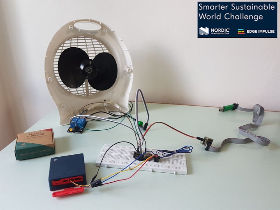
Electronic devices such as refrigerators, air conditioners and fans, which are large energy consumers, may have failures during their lifetime for various reasons, causing its breakage or increase in energy consumption. Timely maintenance can help extend the equipment life if the faults are detected and solved. The aim of this project is to design an energy monitor applying Machine Learning techniques, specifically anomaly detection algorithms, to detect malfunctions in the motor operation.
📢 Warning! Voltages and currents that are dangerous to health are used in this project. If you want to replicate this work, be careful!
The designed monitor is capable of detect the occurrence of an obstruction of the motor, which allows the on-time disconnection of the energy to avoid breakages due the current overconsumption.
An ACS712 sensor is used to measure current consumption. This is a low cost sensor that allows accurate AC or DC measurements. The packaging is very simple consisting of only three terminals: GND, VCC, and OUTPUT. The output is analog so it is necessary to carry out the subsequent analog-digital conversion to obtain the measurement value. In this project, a 220V/50Hz fan motor is used to perform the tests.
The chosen board is Nordic Thingy:53. This is a very easy to use and computationally powerful IoT prototyping platform. It consists of an nRF5340 SoC that has a double ARM Cortex-M33 processor, which allows the implementation of machine learning algorithms.
The Edge Impulse online platform is also used to acquire the measurements, create the model, and perform the deployment in the form of the C++ library, to be consumed locally in the Thingy:53.
Training the Machine Learning ModelAn anomaly detection model is used for this application. The first step consists of acquiring the measurements under normal conditions, that is, without obstructions in the fan for a considerable period. In this way, the model can detect and distinguish between normal operation and when the system parameters are out of range.
The figure shows the data acquired in a measurement of about 20 minutes. It can be seen that all the measurements are grouped around 100mA RMS.
The next step is to create the model or impulse. For this, the training data is configured with the default values, which are a window size of 3000ms (15 samples captured at 5Hz) and a window increment of 1000ms (5 samples steps).
Spectral Analysis was chosen as a processing block since frequency information will be used to discover anomalies and Anomaly Detection using the K-means algorithm as an analysis block.
After processing the input data, the learning block is defined by taking as features those recommended by Edge Impulse, as can be seen in the following figure.
Before carrying out the deployment of the model, some tests were performed with measurements other than those of the training, and the correct operation in the detection of anomalies was verified. The trained model returns a numerical value with the possibility of occurrence of the anomalies, through the trial and error method, the detection threshold was set at 0.4.
Although Edge Impulse allows us to export our model in a firmware directly to the Thingy:53, I decided to export it in C++ library format, since this microcontroller must perform other operations apart from machine learning inference.
Building the hardware🛠️ Challenge #1 founded: The original idea was to only use the Thingy:53 in conjunction with the ACS712 sensor and the Relays Boards, but when I put my hands on the board, I realized that it only had the Qwiic/Stemma QT port!
Arduino to the rescue!
To solve this problem, I decided to use an Arduino Pro Mini to drive both the ACS712 sensor and the Relay Boards. This microcontroller would be controlled by the Thingy:53 through Two-Wire Interface (TWI) communication. For this, the Qwiic cable was cut and adapted to standard breadboard connectors. The Arduino works in this case as a Peripheral and the Thingy:53 as Controller.
🔔 Note: Peripheral and Controller? What happened to the Master and Slave? For a long time, the electronics industry has been using a lexicon embarrassingly out of date with modern standards, this is why the names of communication buses have changed, for the better!
In this section, I’m only going to comment on some of the problems and the most interesting parts of the code. The rest of it can be found in the GitHub repository at the bottom of this page. I strongly recommend the Nordic Academy, as many important concepts are taught in the courses available on that site.
For the Arduino, the code should perform the following functions:
- Start TWI communication in peripheral mode.
- Start the ACS712.h library.
- Constantly sensing the current consumption value.
- Upon receiving a command from the controller, change the state of the relays and/or return the measurement result.
🛠️ Challenge #2 founded: When reading the documentation about the TWI functions and protocol, I discovered that only byte data is allowed to be sent, but the current sensor returns the reading in float!
Union to the rescue!
Studying on the Internet, I found that the C language has a special data type called union that allows you to store different types of data in the same memory location. A union can be defined with different members, but only one can hold a value at a time. This allows us to perform the conversion from float to byte automatically and efficiently. The definition of our union is as follows:
static union FloatI2C {
    float m_float;
    uint8_t m_bytes[sizeof(float)];
} data;
The standard size of the float type is 4 bytes, being compatible on both platforms (Arduino AVR and Thingy:53 ARM) so communication and conversion from one data type to another do not offer any problem.
To convert data from one format to another, simply modify one of the members, as shown in the following code snippet:
data.m_float = mA; // saving in float, automatically is converted to a byte arrayThe functionalities of Thingy:53 consist of:
- Read the data returned by the Arduino through the TWI port.
- Run the machine learning model with 15 samples (3000ms window) every 5 samples (200ms) as it was trained on the Edge Impulse platform.
- If an anomaly is detected, order the power to be disconnected by turning off the relays.
- If an anomaly has occurred, pressing the button on Thingy:53 should connect power to the motor again.
For Thingy:53 programming, use Visual Studio Code in conjunction with the nRF SDK Connect.
Some important considerations:
In order to run the machine learning model created in Edge Impulse, it is necessary to enable support for C++, since by default only C is used. For this, it is necessary to add the following lines to the prj.conf configuration file:
# increase the stack size
CONFIG_MAIN_STACK_SIZE=8192
# enable c++ support
CONFIG_CPLUSPLUS=y
CONFIG_LIB_CPLUSPLUS=y
CONFIG_NEWLIB_LIBC=y
CONFIG_NEWLIB_LIBC_FLOAT_PRINTF=y
CONFIG_FPU=y
# enable the twi bus
CONFIG_I2C=y
The last line is to enable TWI communication.
🛠️ Challenge #3 founded: Where are my lines? By default, the TWI interface lines for the QWIIC connector are not active, so it is necessary to create an overlay file to activate this connection, following the device tree definition used by Thingy:53. Reading the Nordic documentation can be found that the terminals for the expansion port are internally connected to pins P0.4 and P0.5.
In the overlay file:
// configuring the twi port
&pinctrl {
    i2c1_exp: i2c1_exp {
        group1 {
            psels = <NRF_PSEL(TWIM_SDA, 0, 5)>, //P0.5 -> SDA EXP_BOARD (Blue)
                    <NRF_PSEL(TWIM_SCL, 0, 4)>; //P0.4 -> SCL EXP_BOARD (Yellow)
        };
    };
};

&i2c1 {
    status = "okay";
    pinctrl-0 = <&i2c1_exp>;
    clock-frequency = <I2C_BITRATE_STANDARD>;
    mysensor: mysensor@9a {
        compatible = "i2c-device";
        reg = <0x9a>;
        label = "MYSENSOR";
    };
};
In this configuration, a peripheral device connected to address 0x9A (154 in decimal) is defined, the same address that was used in the Arduino.
The code is started by inserting the library code returned by Edge Impulse.
#include "ei-model/edge-impulse-sdk/classifier/ei_run_classifier.h"
#include "ei-model/edge-impulse-sdk/dsp/numpy.hpp"
The code continues with the necessary instructions to handle the led and the button on the board.
In the main function, an infinite loop is created that constantly asks the Arduino to read the ACS712 sensor:
ret = i2c_write_read_dt(&dev_i2c, config, sizeof(config), num.m_bytes, 4);
put(num.m_float);
The put function, previously created, allows inserting the readed samples into an array with a max capacity of 15. This insertion follows a circular format, overwriting past values, in this way the machine learning model can be run as if a window were scrolling every 5 samples. A counter variable is used to verify that for every 15 samples, the analysis should be performed.
// anomaly edge-impulse
get_buffer(features, BUF_SIZE);
signal_t features_signal;
features_signal.total_length = sizeof(features) / sizeof(features[0]);
features_signal.get_data = &raw_features_get_data;

// invoke the impulse
EI_IMPULSE_ERROR res = run_classifier(&features_signal, &result, true);

if (result.anomaly < 0.4)  // the threshold for anomaly
    gpio_pin_set_dt(&led, 0); // led off
else
{
    gpio_pin_set_dt(&led, 1); // led on, anomaly detected
    config[0] = 0;
    i2c_write_dt(&dev_i2c, config, sizeof(config));
    anomalyDetected = true;
}
First, the samples are retrieved with the get_buffer function, which, like put, was created for the work of the circular array. The machine learning model is executed through the functions provided by the library generated by Edge Impulse. For more information on this aspect see https://docs.edgeimpulse.com/docs/deployment/running-your-impulse-locally/running-your-impulse-locally-zephyr.
If the result of the classification is greater than 0.4 (a value that was defined in Edge Impulse as the threshold to detect the anomaly), then the relays are deactivated, turning off the motor, and the detected anomaly flag is activated. This causes Thingy:53 not to request more samples from the Arduino. Only by pressing the button on the board is the whole process started again.
Result and final thoughsThe following video shows the device in operation, it can be seen that, when detecting an obstruction in the motor, the power is disconnected and the LED on the board lights up. Only by pressing the button on Thingy:53 again does the motor start up again.
Some extra features that would be interesting to try in the future:
- Establish Bluetooth communication with an application or PC, which allows an alert to be sent when an anomaly is detected.
- Use an ACS712 sensor with better precision, so that the current consumed can be recorded and sent in real-time, to track energy consumption.
🔔 Note: The ACS712 sensor can be purchased in various formats depending on the maximum current it can measure. There are versions for 5A, 20A, or 30A. The higher the maximum current, the lower the sensitivity. For this prototype, the 30A variant was tested. Once the project was finished, it was determined that this configuration was not the most efficient option for the motor used in the test. As a final recommendation, always make sure of the consumption range of the equipment you want to measure before making your choice.
I hope you enjoy this project and do not forget to leave your comments and feedback!
Diagram
Arduino - Thingy:53: Blue = SDA, Yellow = SCL, Black = GND
Arduino - ACS712: Purple = VCC, Brown = OUTPUT, White = GND
Arduino - Relay board: Green = VCC, Gray, White = CONTROL, Brown = GND.
Power outlet - Relay board : Black = to common pin in relay.
Relay Board - Motor: Gray = from NO (normally open) in relay to motor.
Relay Board - ACS712: Black = from NO (normally open) in relay to screw terminal in ACS712.
ACS712 - Motor: Gray = from the other screw terminal in ACS712 to motor.


_3u05Tpwasz.png?auto=compress%2Cformat&w=40&h=40&fit=fillmax&bg=fff&dpr=2)
Comments
Please log in or sign up to comment.