You ever walk into a room and wish the lights turned on for you? With the ease of use of the motion sensor/vibration sensor the lights will automatically be turned on the moment you enter. The motion sensor is located by the door that way when you pass through it triggers a motor to flip the switch. Additionally, there is a vibration sensor that can be trigged from footsteps as an additional backup. With the application of the automatic light switch never again will you need to manually turn on the lights.
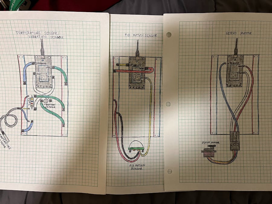
For this project, we had three breadboards that were able to hold the three argons (and other components) in order for them to communicate with each other via code on WebIDE.
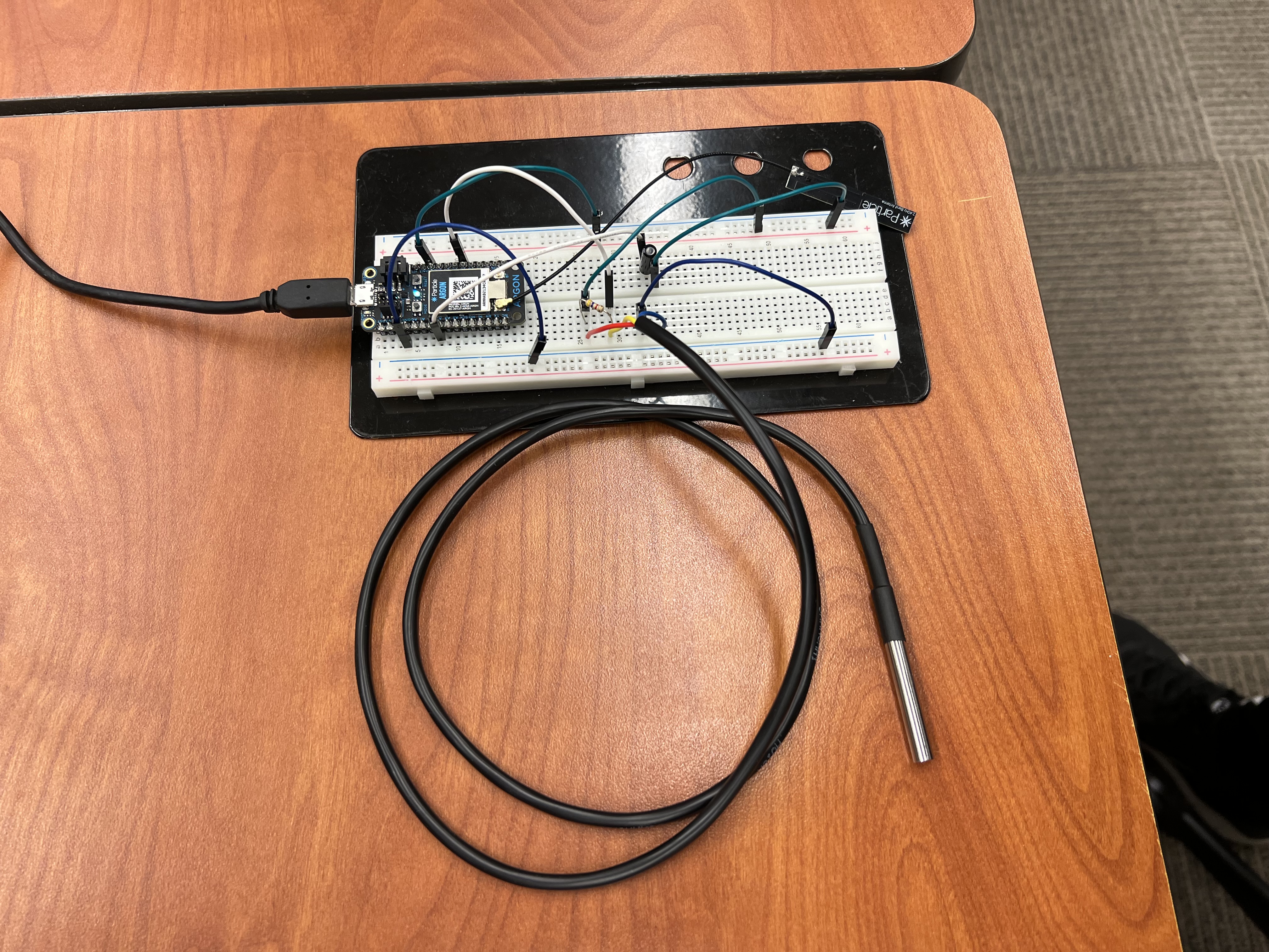
The first breadboard consisted of one argon along with the temperature sensor, vibration sensor and one 4.6k ohm resistor. All these were connected with jumper wires. The purpose of this circuit was to collect temperature data and display it in the charts below as well as be a vibration sensor for incoming footsteps to trigger the light switch.
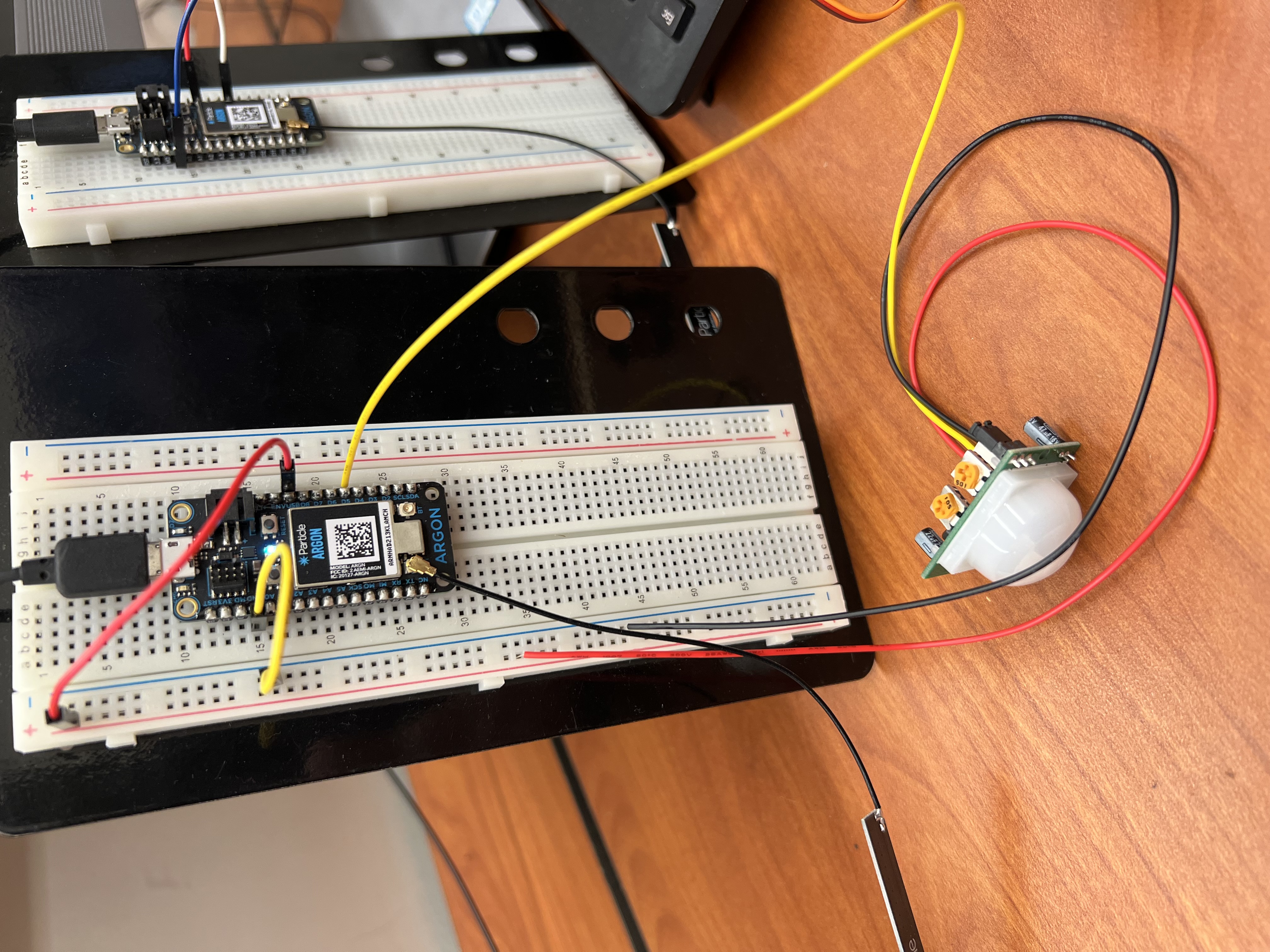
The second breadboard consisted of the second argon along with a PID motion sensor (again connected with jumper wires). The purpose of this circuit was to detect movement/motion coming through the doorway to turn on the lights.
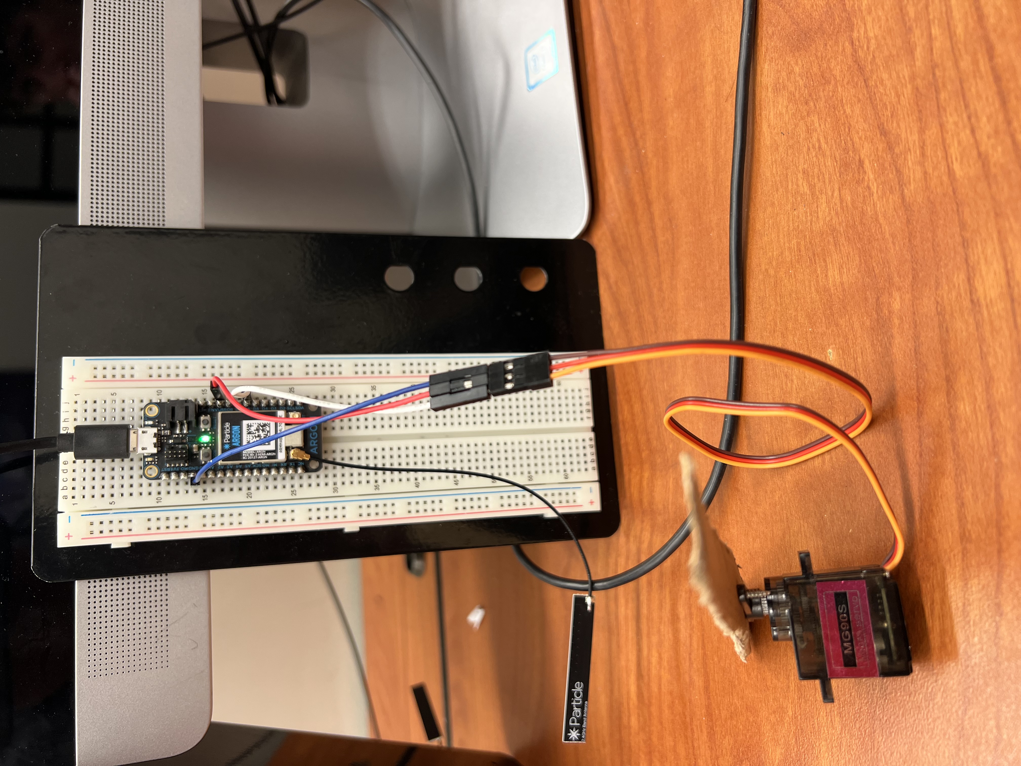
The last breadboard consisted of the last (third) argon as well as a servo motor. This breadboard was rigged to the wall next to the outlet plate and light switch that way when either or both the motion sensor or the vibration sensor was alerted, the servo motor would flip the light switch and in conclusion turn on the lights.
Furthermore, below is temperature data taken from the temperature sensor which allows you to track temperature in the room at any time.
Time vs. Temperature Graph


_zhWsCcSEcl.jpg?auto=compress%2Cformat&w=48&h=48&fit=fill&bg=ffffff)


_aoxOuOFoZ1.jpg)
_jyGGRFG7N0.jpg)
_BWbQqlWxMx.jpg)


_aoxOuOFoZ1.jpg)
_jyGGRFG7N0.jpg)
_BWbQqlWxMx.jpg)
Comments
Please log in or sign up to comment.