You may download the project files here.
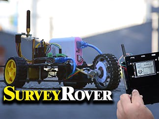
This Survey Rover project is perfect for researchers, educators and hobbyists alike. Using 2.4" gen4 HMI distance module mounted on a hand-held RF controller this surveyor has the ability to store the measured distance.
Step 1: Build
No external circuit is required for this Project.
Step 2: Program
- Extract the contents of the files.
- Copy the nRF905 library file to the Arduino library location.
- Open the project file for Rover using Arduino IDE. This contains the code for the Arduino Uno in the rover car.
- You can check and modify the transceiver address of the rover’s radio module.
- You can check and modify the codes for the rover movement routines here
- Open the project file Controller using Arduino IDE. This contains the codes for the Arduino Uno in the handheld controller.
- You can also check and modify the codes for the data receiving and timeout on the controller side.
- You can also check and modify the codes for assembling the data to be sent to the display here.
- You can check and modify the codes for the joystick commands here.
- Open the Controller Display file using Workshop 4. This project uses the Visi Environment. This contains the code for the display on the handheld controller.
- You can modify the properties of each widget.
- You can check and modify codes for receiving serial commands from the Arduino controller and the odometer routine here.
- You can check and modify the speedometer function shown in the snippet below.
- You can check and modify the codes for showing the data results on the display.
- You can check and modify the codes for converting encoder data to speed and distance measurements in English and metric units.
Step 3: Compile
- Click on the “Compile” button.
Note: This step could be skipped. However, compiling is essential for debugging purposes.
Step 4: Comms Port
Connect the display to the PC. Make sure that you are connected to the right port. Red Button indicates that the device is not connected, Blue Button indicates that the device is connected to the right port.
Step 5: Compile and Upload
- Go back to “Home” tab. This time, click on the “Comp’nLoad” button.
- Workshop 4 IDE will prompt you to select a drive to copy the image files to a uSD Card. After selecting the correct drive, click OK.
Step 5: Mount uSD Card
- The module will prompt you to insert the uSD card.
- Unmount the uSD Card properly from the PC and insert it to the uSD Card slot of the display module.
Video
<iframe width="746" height="480" src="https://www.youtube.com/embed/4SudtdNqO2U" frameborder="0" allow="autoplay; encrypted-media" allowfullscreen></iframe>


_ztBMuBhMHo.jpg?auto=compress%2Cformat&w=48&h=48&fit=fill&bg=ffffff)


Comments
Please log in or sign up to comment.