In my first semester at college, my writing professor took us to the on-campus garden to listen to some music, played by plants. He bought a plant-sonification device from Amazon, and even if we didn't really know how it worked, we were still able to appreciate that a blueberry plant played a different song from a citrus tree.
When presented with this project for an intro electrical engineering course, I wanted to make a similar device that could take capacitive readings from a living thing and make music with it. Here's what I've been able to do in the past month!
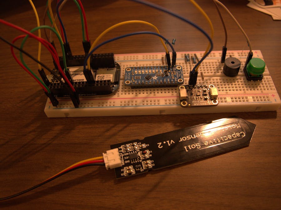
Building Instructions1. Place PocketBeagle on solderless breadboard.
2. Connect rails on both side to ground/3.3V power (as appropriate). I used green wires to indicate ground, and red ones to indicate 3.3V.
3. Connect three male-male jumper wires to the moisture sensor. I color-coordinated to match the provided cable.
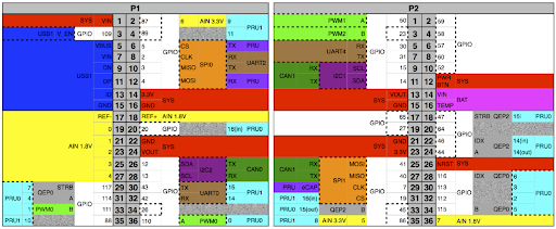
4. Connect the black wire to ground, the red wire to 3.3V, and the yellow wire to an AIN pin. I used P1_2 (AIN6).
5. Place the capacitive touch sensor on the breadboard, and wire it as shown. Connect Vin to 3.3V and GND to ground. I used 1kΩ resistors to connect the SDA and SCK pins each to 3.3V.
6. Use two jumper cables to connect the SDA and SCK pins to the PocketBeagle. I used a blue cable to connect the SDA pin to P2_11 and a yellow one to connect the SCK pin to P2_9.
7. Place the light sensor on the breadboard and wire as shown. Connect Vin to 3.3V and GND to ground. I used 4.7kΩ resistors to connect the SDA and SCL pins each to 3.3V.
8. Use two jumper cables to connect the SDA and SCL pins to the PocketBeagle. I used a blue cable to connect the SDA pin to P1_26 and a yellow one to connect the SCL pin to P1_28.
9. Place the buzzer on the breadboard and wire as shown. The (+) pin should go to the PocketBeagle. I used a brown cable to connect it to P2_1. The other pin should go to ground.
10. Place the button on the breadboard and wire as shown. One pin should go to the PocketBeagle and connect to 3.3V with a 1kΩ resistor. I used a white wire to connect to P2_2. The other pin should go to ground.
11. Finally, place a cable connecting to the touch sensor's C1 pin. The free end of the cable will go to the living thing and measure its capacitive touch readings!
The overall wiring should look like this:
(For more detailed instructions and explanations, go to the Plant Music github!)
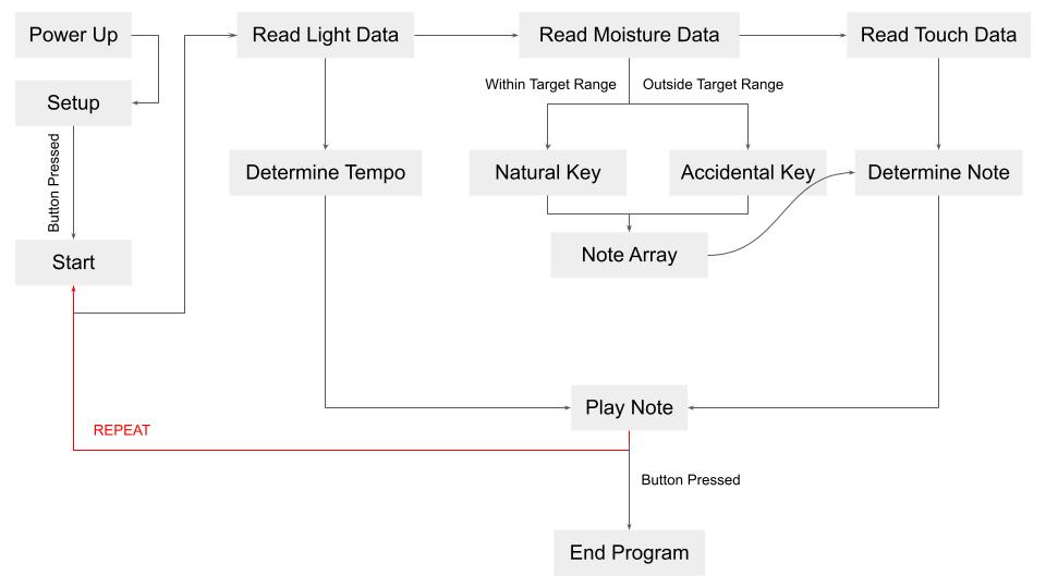
If automatic booting is implemented, the program should boot upon powerup. From there, press the button to start the program, and press and hold to stop the program. In order to restart, the device has to be completely rebooted.
Video demonstrating overall function:
Steps Shown in Video:
1. Start the program by pressing the button.
2. Have finger on C1 wire to measure capacitive readings.
3. Cover moisture sensor with wet paper tower to emulate wet soil. Notice drop in accidental occurrence.
4. Shine additional light to raise tempo.
5. Hold button to stop program
Potential Future Steps:Currently, the touch sensor is extremely sensitive: even touching the breadboard or hovering near the wire triggers it. One potential improvement would be to figure out how to decrease its sensitivity.
Additionally, the touch readings do not directly correspond to certain notes. Though they do impact which group of notes can be played, it would be interesting to link certain raw touch readings to certain notes or otherwise make the notes produced more humanly musical.


Comments
Please log in or sign up to comment.