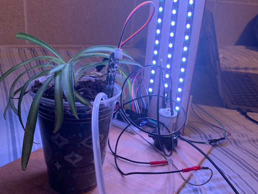
I've personally always enjoyed having plants so when I came to college, I thought it would be nice to grow some in my room. After going on vacation for spring break, I returned to my dorm to find my plants wilting away. This inspired me to create this project to create a device that can supply essential nutrients like water and light to the plant according to when it needs it. This allows for me to not need to be constantly watering because the capacitive soil sensor automatically will detect when it needs to be watered and it doesn't require me to have to take my plants in and outside because they can always get enough light with the LED strips.
Breadboard SetupI knew initially that every component in my project would be connected to the Pocketbeagle so in setting up my board, I initially had placed the PB at the top and connected the various components to the board below. With 6 components to get working, however, I decided it would be best to separate the PB on a half board and add the components separately on the full board. Here's a breakdown of each component I used, how I wired it to the board and where I connected it on the PB.
1. PocketBeagle
- First the PocketBeagle must have headers soldered onto it of not previously done.
- Once soldered, the PB can be secured into the half breadboard
- The PB is connected with a microUSB to the computer
2. Bread Board Power Rails
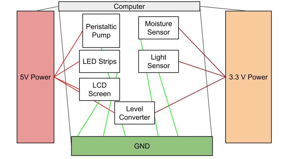
Most components of this project required either at least 3V or 5V Power supply so I decided to create respective power rails to easily supply power to different rows on the breadboard.
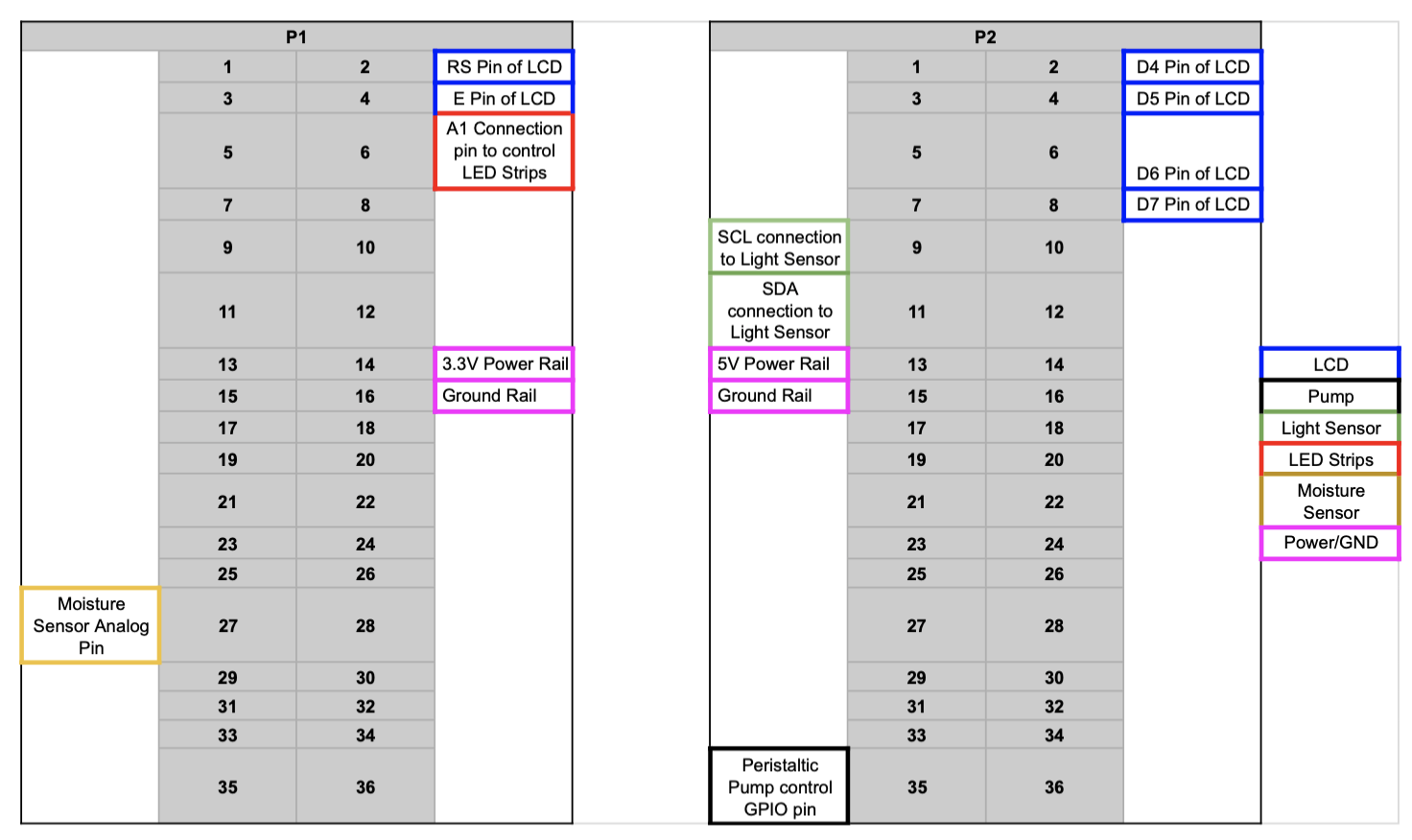
- 5V: Connect a jumper cable from P2_13 (Vout) to the + row (red) on one side of the full breadboard. Connect another cable from P2_15 (GND) to the - row(blue) on the same side.
- 3.3V: Connect a jumper cable from P1_14 (Vout) to the + row (red) on the opposite side of the full breadboard. Connect another cable from P1_16 (GND) to the - row(blue) on the same side.
Now the board can draw power and connect to ground from either side of the board
3. Peristaltic Pump and Digital Switch
The Peristaltic pump only has 2 prongs, one positive terminal, and one negative terminal, indicating it is meant for a constant DC Power Supply. To account for this, I decided to create a digital switch with a transistor to control the pump.
- Solder separate wires for each prong of the pump and use a heat shrink to cover the soldered area.
- At the other end of the wire, crimp together the end of a jumper cable so that it's touching the end of the wire opposite of the pump terminal. Once crimped, apply heat gun to shrink wrap the wires together. Do this for both terminals. This allowed for me to have pins to work with and connect to my breadboard.
- Create the switch circuit by connecting the transistor to the breadboard. Each pin of the transistor should be in its own row. The goal of the transistor is that it will prevent the flow of current when the switch is "off" and return flow when it is turned back "on".
- With the letters of the transistor facing you, the rightmost pin(collector) should be closest to you on the board followed by the second pin in the next row(base) and then furthest away the third pin(emitter)
- Connect a jumper cable from the 5V power row to an empty row next to the collector pin of the transistor. Connect the + terminal jumper of the pump to the same row.
- Connect the jumper cable connected to the negative terminal of the Peristaltic Pump to the collector pin of the transistor (pin closest to you).
- Connect a jumper from P2_35 (GPIO) to another empty row near the transistor.
- Connect a 470 ohm resistor from that same row across to the row of the 2nd pin of the transistor. This will control the switch.
- Add a ground connection to the same row as the final pin of the transistor (emitter)
4. BH1750 Light Sensor
- Solder headers into the holes of the sensor and place onto another part of the breadboard, preferably near the 3.3V row.
- Connect a wire from the 3.3V power rail to Vin on the sensor
- Skip the 3Vo pin row
- Connect a wire from either ground rail and connect to the GND pin of the sensor
- Connect the SCL and SDA pin rows to the 3.3V power rail across a pull up resistor (1k each). In the same row add jumper wires between the resistor and pins on the sensor. You will need one for SCL and one for SDA. Connect the SCL jumper to P2_9 and SDA jumper to P2_11 on the PB.
5. 16x2 LCD Screen and Potentiometer(for contrast adjustment)
- Connect the screen to the breadboard ensuring each pin has a different row
- Connect the VSS,RW, and K pin rows to the ground power rail
- Connect the VDD, and A pin rows to the 5V power rail
- Connect a jumper from RS pin row to P1_2 (GPIO) and the E pin row to P1_4 (GPIO)
- Connect jumpers from D4,D5,D6, and D7 pin rows to respective GPIO pins. (I used P2_2, P2_4, P2_6, P2_8 respectively.
- Lastly connect the potentiometer near the LCD screen with each pin in its own row
- With the indented side facing you, connect the leftmost pin to the 5V power supply and the rightmost pin to ground. Then, connect a wire from the middle pin to the V0 pin on the LCD board
6. LED Light Strips and Level Converter
Converter
- Solder headers onto both sides of the level converter and place it over the middle ridge of the breadboard
- Connect a wire from 3.3V rail to the VA pin row of the converter and a jumper from the A1 pin to P1_6 (GPIO) on the PB.
- Add a wire connecting the VA pin row to the OE pin row. (Yes the wire is on the same side of the converter)
- Connect the VB pin to the 5V power rail and the GND pin to the ground rail
LED Strips
- Connect a jumper wire from the 5V pin on the LED strip to the 5V power rail on the breadboard. Connect another wire from the GND pin of the strip to the ground rail. Lastly, connect another wire from the D0 (data) pin of the strip to B1 pin row on the level converter
7. Capacitive Soil Moisture Sensor
- Connect a jumper from the VCC pin on the sensor to the 3.3 V power rail
- Connect another jumper from the GND pin to the ground rail
- Connect another jumper from the AOUT pin to P1_27 (AIN4) on the PB
- Connect the outflow tube of the pump to your desired location within your plant pot
- Connect the inflow end of the tube to a water source. In my case I used a big water cup and filled it all the way up.
- Stick the bottom of the soil sensor until most of it is covered(stop when you get to the visible electronic components on it
- Set up frame over plant and stick LED strip to it so the lights are facing toward the plant
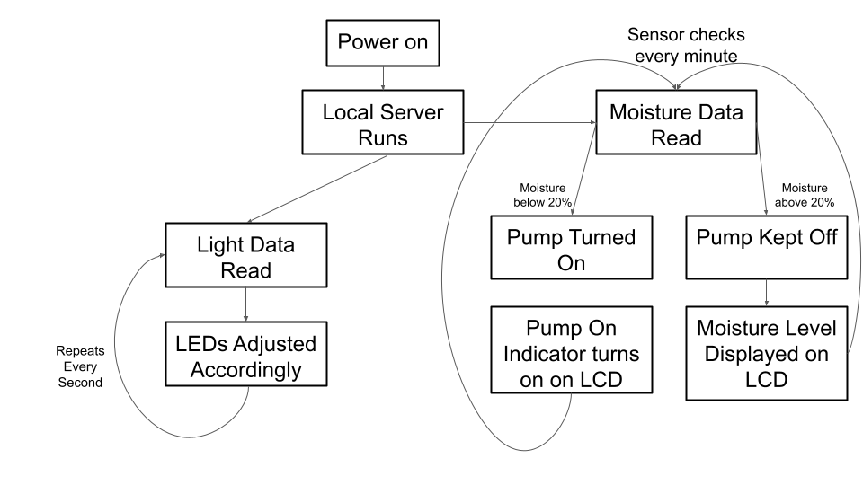
- On boot the device will run on its own with the lights powering on after 30 seconds. The lights will adjust their brightness according to the light sensor readings so if the room is very dark the lights will be maximum brightness and if an overhead light is on, the light will dim or turn entirely off
- Simultaneously, the moisture sensor is detecting the moisture level in the soil to see if/when the pump needs to be turned on to water it. It only turns on when it is 20% moist which was determined after calibrating the device and looking into how wet the soil should be before watering again. The LCD display is intended to display the current moisture level, signal when the pump is running and when it has just turned off.
The software of this device is organized such that each component essentially has a designated class that is called upon in the main to run respective functions
These classes include:
- Light() - Used to output lux readings
- Moisture() - Used to output moisture level readings
- Pump() - Used to control pump and turn it on and off
- LCD() - Used to control LCD screen
Separate functions were created in the main file to execute the actual running of the device. This involved performing threading so that the light and moisture processes could run simultaneously. The code for initializing variables including the LEDs and local host were written in the main as well.
Future PlansWhile I was able to achieve a lot with this project, there are a few things I would like to add/adjust for the future. one thing I considered was allowing the user to adjust what color they wanted the lights to be. This intent of this would be to adapt to plants that thrive with different light frequencies. A more achievable plan is to cleanup the circuit and make everything neater. Some wires are very lengthy and tangled, both of which can be easily fixed. I also considered other sensors like a pH sensor and temperature sensor which would control objects that could modify these metrics which would make the device and the associated plant truly autonomous.


Comments
Please log in or sign up to comment.