Hardware components | ||||||
_ztBMuBhMHo.jpg?auto=compress%2Cformat&w=48&h=48&fit=fill&bg=ffffff) |
| × | 1 | |||
 |
| × | 1 | |||
 |
| × | 1 | |||
| × | 1 | ||||
Software apps and online services | ||||||
 |
| |||||
 |
| |||||
 |
| |||||
Hand tools and fabrication machines | ||||||
 |
| |||||
 |
| |||||
 |
| |||||
Hello,
In this project, I created a 4-way traffic light system using an Arduino UNO, showcasing how technology can streamline traffic control. With red, yellow, and green LEDs, the system mimics real traffic lights while housed in a creative cardboard enclosure. Assembling the components and writing the code presented some challenges, but I learned valuable skills in coding and circuit design while troubleshooting. Moving forward
This hands-on approach not only highlights coding and circuitry skills but also opens the door to future upgrades, like adding sensors for smarter traffic management. It's a fun way to explore innovation in urban systems!
Thank You
Arduino Traffic Light Design
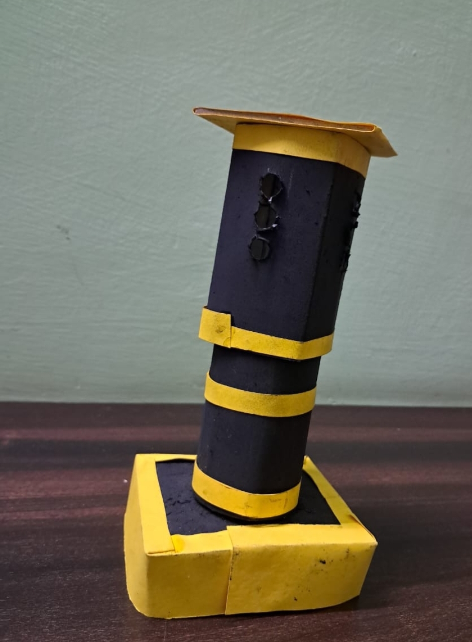
CARDBOARD ENCLOSURE
The traffic light system is housed in a cardboard enclosure to protect the Arduino and LEDs, keeping wiring organized and stable.
CUSTOM CUTOUTS
Openings for LEDs allow light to shine through clearly.
Optional ventilation cutouts can be added for airflow.
ASSEMBLY
Cardboard was cut to fit components and assembled using glue and tape for stability.
DESIGN CONSIDERATION
The lightweight cardboard design allows for easy modifications and is cost-effective for future projects.

Arduino Traffic Light Circuit
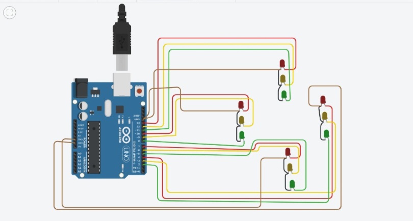
SCHEMATIC OVERVIEW
The circuit connects four sets of LEDs (red, yellow, and green) to specific pins on the Arduino. Each LED corresponds to a traffic light direction and operates based on the programmed logic.
CONNECTIONS
LED Connections:
Red LEDs: Connected to pins 13, 10, 7, and 4
Yellow LEDs: Connected to pins 12, 9, 6, and 3
Green LEDs: Connected to pins 11, 8, 5, and 2
POWER SUPPLY
Powered directly from the Arduino, ensuring that the LEDs receive the necessary voltage to operate.
CIRCUIT LOGIC
The circuit operates by sequentially lighting up the green, yellow, and red LEDs in a specified order to simulate traffic lights for four directions. The logic is defined in the code, ensuring that traffic is controlled efficiently.

Arduino Code for 4-Way Traffic Light Control
C/C++Each function (case1 to case8) represents a different traffic light scenario, managing the LED states for each direction.
Delays between each case ensure proper timing, simulating real traffic light behavior.
Delays between each case ensure proper timing, simulating real traffic light behavior.
// Define pin numbers for each traffic light color for all four directions
int red1 = 13;   // Red light for direction 1
int yellow1 = 12; // Yellow light for direction 1
int green1 = 11;  // Green light for direction 1
int red2 = 10;   // Red light for direction 2
int yellow2 = 9; // Yellow light for direction 2
int green2 = 8;  // Green light for direction 2
int red3 = 7;    // Red light for direction 3
int yellow3 = 6; // Yellow light for direction 3
int green3 = 5;  // Green light for direction 3
int red4 = 4;    // Red light for direction 4
int yellow4 = 3; // Yellow light for direction 4
int green4 = 2;  // Green light for direction 4

void setup() {
  // Set each pin as an OUTPUT
  pinMode(red1, OUTPUT);
  pinMode(yellow1, OUTPUT);
  pinMode(green1, OUTPUT);
  pinMode(red2, OUTPUT);
  pinMode(yellow2, OUTPUT);
  pinMode(green2, OUTPUT);
  pinMode(red3, OUTPUT);
  pinMode(yellow3, OUTPUT);
  pinMode(green3, OUTPUT);
  pinMode(red4, OUTPUT);
  pinMode(yellow4, OUTPUT);
  pinMode(green4, OUTPUT);
}

// Function to turn on green light for direction 1 and red for others
void case1() {
  digitalWrite(red1, LOW);
  digitalWrite(yellow1, LOW);
  digitalWrite(green1, HIGH);
  digitalWrite(red2, HIGH);
  digitalWrite(yellow2, LOW);
  digitalWrite(green2, LOW);
  digitalWrite(red3, HIGH);
  digitalWrite(yellow3, LOW);
  digitalWrite(green3, LOW);
  digitalWrite(red4, HIGH);
  digitalWrite(yellow4, LOW);
  digitalWrite(green4, LOW);
}

// Function for yellow light for direction 1
void case2() {
  digitalWrite(red1, LOW);
  digitalWrite(yellow1, HIGH);
  digitalWrite(green1, LOW);
  digitalWrite(red2, HIGH);
  digitalWrite(yellow2, LOW);
  digitalWrite(green2, LOW);
  digitalWrite(red3, HIGH);
  digitalWrite(yellow3, LOW);
  digitalWrite(green3, LOW);
  digitalWrite(red4, HIGH);
  digitalWrite(yellow4, LOW);
  digitalWrite(green4, LOW);
}

// Function to turn on green light for direction 2
void case3() {
  digitalWrite(red1, HIGH);
  digitalWrite(yellow1, LOW);
  digitalWrite(green1, LOW);
  digitalWrite(red2, LOW);
  digitalWrite(yellow2, LOW);
  digitalWrite(green2, HIGH);
  digitalWrite(red3, HIGH);
  digitalWrite(yellow3, LOW);
  digitalWrite(green3, LOW);
  digitalWrite(red4, HIGH);
  digitalWrite(yellow4, LOW);
  digitalWrite(green4, LOW);
}

// Function for yellow light for direction 2
void case4() {
  digitalWrite(red1, HIGH);
  digitalWrite(yellow1, LOW);
  digitalWrite(green1, LOW);
  digitalWrite(red2, LOW);
  digitalWrite(yellow2, HIGH);
  digitalWrite(green2, LOW);
  digitalWrite(red3, HIGH);
  digitalWrite(yellow3, LOW);
  digitalWrite(green3, LOW);
  digitalWrite(red4, HIGH);
  digitalWrite(yellow4, LOW);
  digitalWrite(green4, LOW);
}

// Function to turn on green light for direction 3
void case5() {
  digitalWrite(red1, HIGH);
  digitalWrite(yellow1, LOW);
  digitalWrite(green1, LOW);
  digitalWrite(red2, HIGH);
  digitalWrite(yellow2, LOW);
  digitalWrite(green2, LOW);
  digitalWrite(red3, LOW);
  digitalWrite(yellow3, LOW);
  digitalWrite(green3, HIGH);
  digitalWrite(red4, HIGH);
  digitalWrite(yellow4, LOW);
  digitalWrite(green4, LOW);
}

// Function for yellow light for direction 3
void case6() {
  digitalWrite(red1, HIGH);
  digitalWrite(yellow1, LOW);
  digitalWrite(green1, LOW);
  digitalWrite(red2, HIGH);
  digitalWrite(yellow2, LOW);
  digitalWrite(green2, LOW);
  digitalWrite(red3, LOW);
  digitalWrite(yellow3, HIGH);
  digitalWrite(green3, LOW);
  digitalWrite(red4, HIGH);
  digitalWrite(yellow4, LOW);
  digitalWrite(green4, LOW);
}

// Function to turn on green light for direction 4
void case7() {
  digitalWrite(red1, HIGH);
  digitalWrite(yellow1, LOW);
  digitalWrite(green1, LOW);
  digitalWrite(red2, HIGH);
  digitalWrite(yellow2, LOW);
  digitalWrite(green2, LOW);
  digitalWrite(red3, HIGH);
  digitalWrite(yellow3, LOW);
  digitalWrite(green3, LOW);
  digitalWrite(red4, LOW);
  digitalWrite(yellow4, LOW);
  digitalWrite(green4, HIGH);
}

// Function for yellow light for direction 4
void case8() {
  digitalWrite(red1, HIGH);
  digitalWrite(yellow1, LOW);
  digitalWrite(green1, LOW);
  digitalWrite(red2, HIGH);
  digitalWrite(yellow2, LOW);
  digitalWrite(green2, LOW);
  digitalWrite(red3, HIGH);
  digitalWrite(yellow3, LOW);
  digitalWrite(green3, LOW);
  digitalWrite(red4, LOW);
  digitalWrite(yellow4, HIGH);
  digitalWrite(green4, LOW);
}

void loop() {
  case1();  // Green light for direction 1
  delay(5000);  // Wait for 5 seconds

  case2();  // Yellow light for direction 1
  delay(2000);  // Wait for 2 seconds

  case3();  // Green light for direction 2
  delay(5000);  // Wait for 5 seconds

  case4();  // Yellow light for direction 2
  delay(2000);  // Wait for 2 seconds

  case5();  // Green light for direction 3
  delay(5000);  // Wait for 5 seconds

  case6();  // Yellow light for direction 3
  delay(2000);  // Wait for 2 seconds

  case7();  // Green light for direction 4
  delay(5000);  // Wait for 5 seconds

  case8();  // Yellow light for direction 4
  delay(2000);  // Wait for 2 seconds
}
42 projects • 61 followers
Working as Director of Innovation Centre at Manav Rachna, India. I am into development for the last 12 years.


_t9PF3orMPd.png?auto=compress%2Cformat&w=40&h=40&fit=fillmax&bg=fff&dpr=2)


Comments
Please log in or sign up to comment.