


Hardware components | ||||||
 |
| × | 1 | |||
 |
| × | 1 | |||
 |
| × | 1 | |||
 |
| × | 1 | |||
 |
| × | 1 | |||
 |
| × | 1 | |||
 |
| × | 1 | |||
Software apps and online services | ||||||
 |
| |||||
 |
| |||||
𝙸𝚗𝚝𝚛𝚘𝚍𝚞𝚌𝚝𝚒𝚘𝚗 - 𝙰 𝚂𝚖𝚊𝚛𝚝𝚎𝚛 𝚆𝚊𝚢 𝚃𝚘 𝙶𝚊𝚝𝚑𝚎𝚛 𝙿𝚞𝚋𝚕𝚒𝚌 𝙾𝚙𝚒𝚗𝚒𝚘𝚗
In today’s fast-paced world, real-time feedback is essential for improving services. Traditional surveys are slow and ignored, but what if feedback could be instant, effortless, and smart? Introducing SmartSense, an innovative public review system powered by sensors that collect feedback without manual input !
𝙺𝚎𝚢 𝙼𝚎𝚛𝚒𝚝𝚜 - 𝚆𝚑𝚢 𝚂𝚖𝚊𝚛𝚝𝚂𝚎𝚗𝚜𝚎 ?
🔹 𝗧𝗼𝘂𝗰𝗵𝗹𝗲𝘀𝘀 & 𝗔𝘂𝘁𝗼𝗺𝗮𝘁𝗶𝗰 – Sensors detect user response, eliminating the need for buttons.
🔹 𝗥𝗲𝗮𝗹 𝗧𝗶𝗺𝗲 𝗗𝗮𝘁𝗮 𝗜𝗻𝘀𝗶𝗴𝗵𝘁𝘀 – Instantly sends data to ThingSpeak for live analysis.
🔹 𝗔𝗜-𝗥𝗲𝗮𝗱𝘆 – Can integrate with analytics for predictive insights.
🔹 𝗦𝗰𝗮𝗹𝗮𝗯𝗶𝗹𝗶𝘁𝘆 𝗮𝗻𝗱 𝗩𝗲𝗿𝘀𝗮𝗹𝗶𝘁𝘆 – Works in malls, stations, offices, and public spaces.
🔹 𝗨𝘀𝗲𝗿-𝗙𝗿𝗶𝗲𝗻𝗱𝗹𝘆 – No apps, no QR codes—just real-world interaction.
🔹 𝗙𝗹𝗲𝘅𝗶𝗯𝗹𝗲 – Can be expanded with more sensors and data points.
🔹 𝗟𝗼𝘄 𝗟𝗮𝘁𝗲𝗻𝗰𝘆 𝗖𝗼𝗺𝗺𝘂𝗻𝗶𝗰𝗮𝘁𝗶𝗼𝗻 – Fast data transmission ensures instant feedback updates.
🔹 𝗦𝗲𝗰𝘂𝗿𝗲 𝗗𝗮𝘁𝗮 𝗛𝗮𝗻𝗱𝗹𝗶𝗻𝗴 – Protects user inputs with encrypted cloud storage
.🔹 𝗣𝗿𝗼𝗺𝗼𝘁𝗲𝘀 𝗖𝗼𝗺𝗺𝘂𝗻𝗶𝘁𝘆 𝗘𝗻𝗴𝗮𝗴𝗲𝗺𝗲𝗻𝘁𝘀 – Encourages public participation in service improvements.
🔹 𝗜𝗻𝘀𝘁𝗮𝗻𝘁 𝘃𝗶𝘀𝘂𝗮𝗹 𝗙𝗲𝗲𝗱𝗯𝗮𝗰𝗸– LEDs indicate user responses in real-time.
𝙱𝚎𝚑𝚒𝚗𝚍 𝚃𝚑𝚎 𝙸𝚗𝚗𝚘𝚟𝚊𝚝𝚒𝚘𝚗 - 𝙷𝚘𝚠 𝙸𝚝 𝚆𝚘𝚛𝚔𝚜 ?
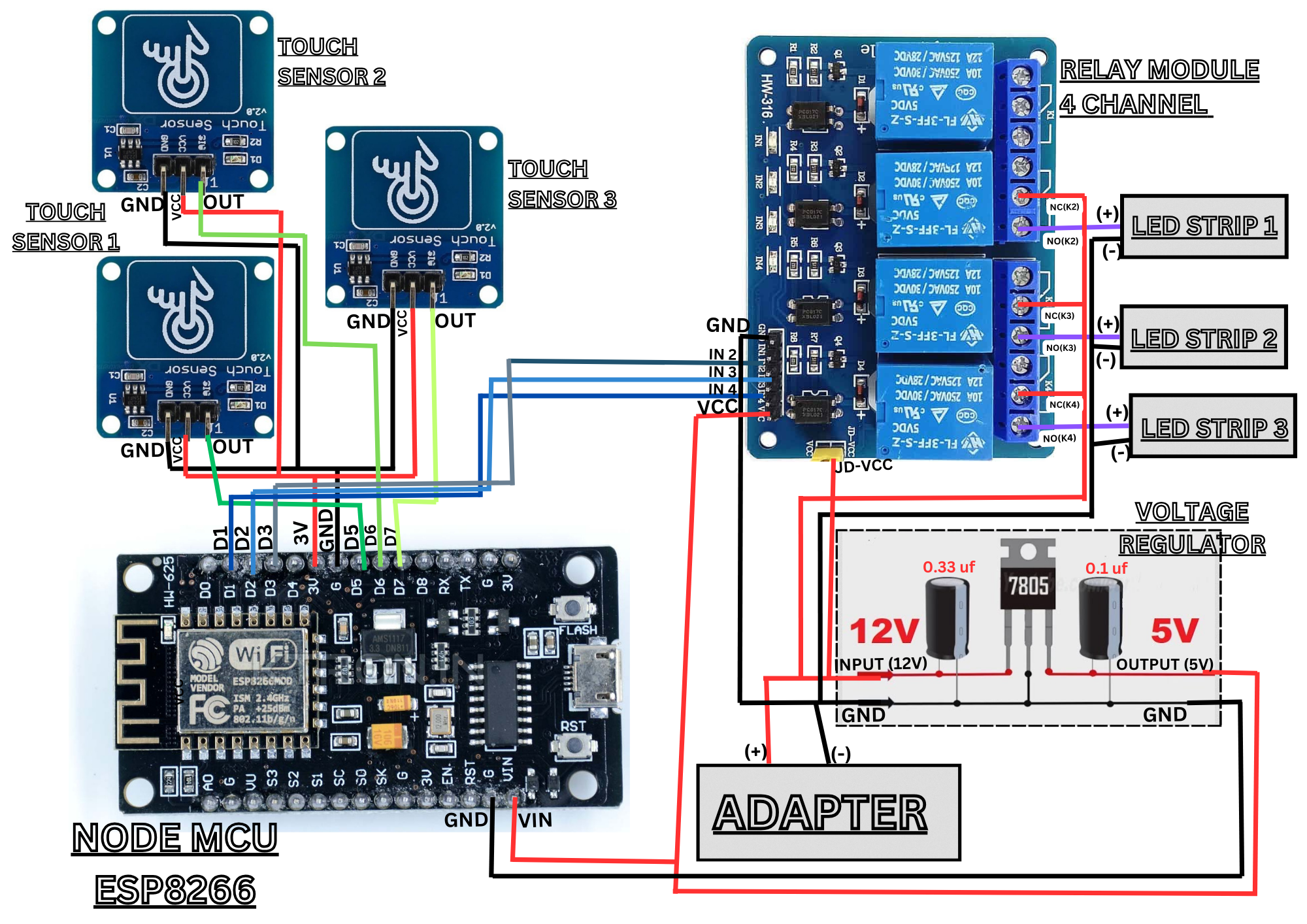
1️⃣ Sensing User Input 🛎️
Sensors (instead of buttons) detect user interactions like touch or proximity.
Each sensor represents a feedback option (e.g., happy, neutral, sad).
2️⃣ Processing the Data 🔄
NodeMCU reads the sensor inputs and updates the count for each response.
Corresponding LEDs briefly turn ON to confirm the feedback is recorded.LEDs then turn OFF to be ready for the next input.
3️⃣ Transmitting Data to the Cloud 📡
NodeMCU sends the feedback data to ThingSpeak over Wi-Fi.
Data is logged in fields corresponding to each feedback type.
4️⃣ Real-Time Data Visualization 📊
ThingSpeak processes the data and displays it in charts and graphs.
Admins can monitor trends in real-time for decision-making.
𝚆𝚑𝚎𝚛𝚎 𝙸𝚝 𝙲𝚊𝚗 𝙱𝚎 𝚄𝚜𝚎𝚍 ?
🏢 𝗦𝗺𝗮𝗿𝘁 𝗥𝗲𝘀𝘁𝗿𝗼𝗼𝗺𝘀 – Hygiene feedback at malls, airports, offices.
🛍️ 𝗥𝗲𝘁𝗮𝗶𝗹 𝗮𝗻𝗱 𝗠𝗮𝗹𝗹𝘀 – Quick customer satisfaction surveys.
🚌 𝗣𝘂𝗯𝗹𝗶𝗰 𝗧𝗿𝗮𝗻𝘀𝗽𝗼𝗿𝘁 – Experience ratings for buses, metros, taxis.
🎭 𝗘𝘃𝗲𝗻𝘁𝘀 𝗮𝗻𝗱 𝗘𝘅𝗵𝗶𝗯𝗶𝘁𝗶𝗼𝗻𝘀 – Instant attendee feedback.
🏥 𝗛𝗼𝘀𝗽𝗶𝘁𝗮𝗹𝘀 𝗮𝗻𝗱 𝗰𝗹𝗶𝗻𝗶𝗰𝘀 – Patient feedback for better healthcare services.
🎓 𝗘𝗱𝘂𝗰𝗮𝘁𝗶𝗼𝗻𝗮𝗹 𝗜𝗻𝘀𝘁𝗶𝘁𝘂𝘁𝗶𝗼𝗻𝘀 – Student opinions on courses, faculty, and facilities.
🎤 𝗖𝗼𝗻𝗰𝗲𝗿𝘁𝘀 𝗮𝗻𝗱 𝗙𝗲𝘀𝘁𝗶𝘃𝗮𝗹𝘀 – Real-time audience experience ratings.
🏨 𝗛𝗼𝘁𝗲𝗹𝘀 𝗮𝗻𝗱 𝗥𝗲𝘀𝗼𝗿𝘁𝘀 – Guest satisfaction surveys for service improvement.
⚖️ 𝗚𝗼𝘃𝗲𝗿𝗻𝗺𝗲𝗻𝘁 𝗢𝗳𝗳𝗶𝗰𝗲𝘀– Citizen feedback on services and policies.
🍽️ 𝗥𝗲𝘀𝘁𝗿𝗮𝘂𝗻𝘁𝘀 𝗮𝗻𝗱 𝗰𝗮𝗳𝗲𝘀 – Quick dining experience reviews.
🏭 𝗙𝗮𝗰𝘁𝗼𝗿𝗶𝗲𝘀 𝗮𝗻𝗱 𝗪𝗼𝗿𝗸𝗽𝗹𝗮𝗰𝗲𝘀 – Employee feedback on safety and work conditions.
🛑 𝗧𝗿𝗮𝗳𝗳𝗶𝗰 𝗮𝗻𝗱 𝗥𝗼𝗮𝗱 𝘀𝗮𝗳𝗲𝘁𝘆 – Public input on traffic conditions and road maintenance.
𝚃𝚑𝚎 𝙵𝚒𝚗𝚊𝚕 𝚅𝚎𝚛𝚍𝚒𝚌𝚝 - 𝚂𝚖𝚊𝚛𝚝, 𝚂𝚒𝚖𝚙𝚕𝚎 𝚊𝚗𝚍 𝙸𝚖𝚙𝚊𝚌𝚝𝚏𝚞𝚕
In a world driven by opinions, real-time feedback is the key to improvement! This Public Review System transforms raw user responses into actionable insights, making decision-making smarter and more efficient. With cloud connectivity, touch-free sensing, and instant data visualization, this project is a game-changer for businesses, public spaces, and smart cities.
Imagine a future where feedback is effortless, data is powerful, and every opinion counts—that future starts now!
𝐒𝐦𝐚𝐫𝐭 𝐏𝐮𝐛𝐥𝐢𝐜 𝐅𝐞𝐞𝐝𝐛𝐚𝐜𝐤 𝐒𝐲𝐬𝐭𝐞𝐦 - 𝐂𝐢𝐫𝐜𝐮𝐢𝐭 𝐎𝐯𝐞𝐫𝐯𝐢𝐞𝐰


Comments
Please log in or sign up to comment.