In an age where interactive technology are becoming increasingly integrated into our daily lives, creating engaging and visually appealing projects can make the learning process both enjoyable and informative. With this in mind, I embarked on building something cute and interactive—a pair of animated eyes that follow the movement of an object using an OLED display and an ultrasonic sensor. The project leverages the power of an Arduino Uno microcontroller, a SSD1351 OLED display, and an HC-SR04 ultrasonic sensor to create a pair of eyes that track the presence and position of an object, such as a finger, in front of the sensor.
Let's Start with OLED DisplaysOrganic light-emitting diode (OLED) displays are relatively new technology, increasingly used in TVs, computer monitors, smartphones, and handheld game consoles. Unlike LCDs, which require backlighting, each OLED pixel generates its own light providing superior contrast and color control.
We will be using the RGB OLED displays from along with using AdaFruit display control and graphics libraries. To do so, we need to install some libraries.
Install Arduino librariesTo use the OLED display, we need two libraries from Adafruit into our IDE:
#include "Adafruit_GFX.h"
The Adafruit_GFX library is a core graphics library provided by Adafruit. It offers a wide range of graphics functions that simplify drawing shapes, text, and images on various displays. Key features of the Adafruit_GFX library include:
- Drawing Shapes: Functions to draw basic shapes like lines, circles, rectangles, and triangles.
- Text Rendering: Functions to render text with different fonts, sizes, and colors.
- Bitmap Images: Functions to display bitmap images.
- Coordinate System: Provides an easy-to-use coordinate system for positioning graphics elements on the screen.
#include "Adafruit_SSD1351.h"
Fortunately, the Arduino IDE makes library installation easy. Take a lookie!
Once you’ve installed the requisite libraries, you’re ready to wire up the display!
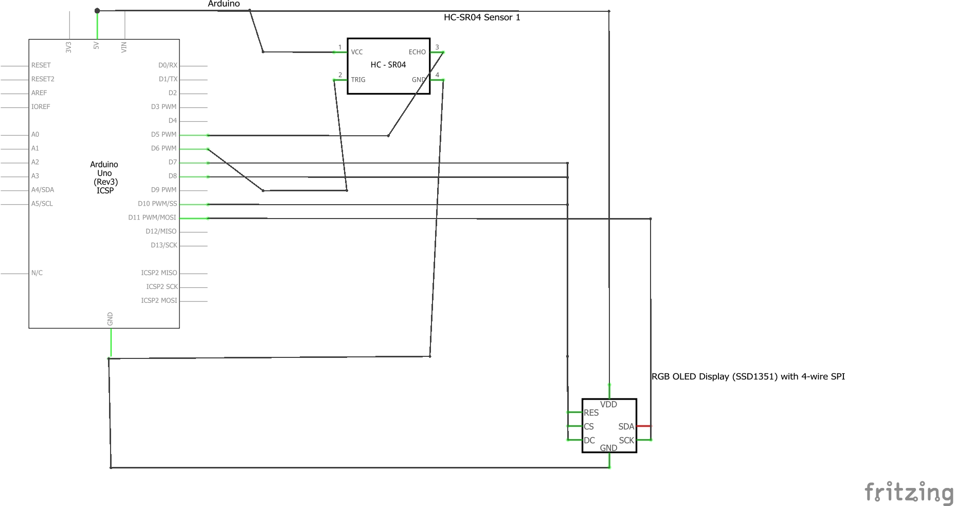
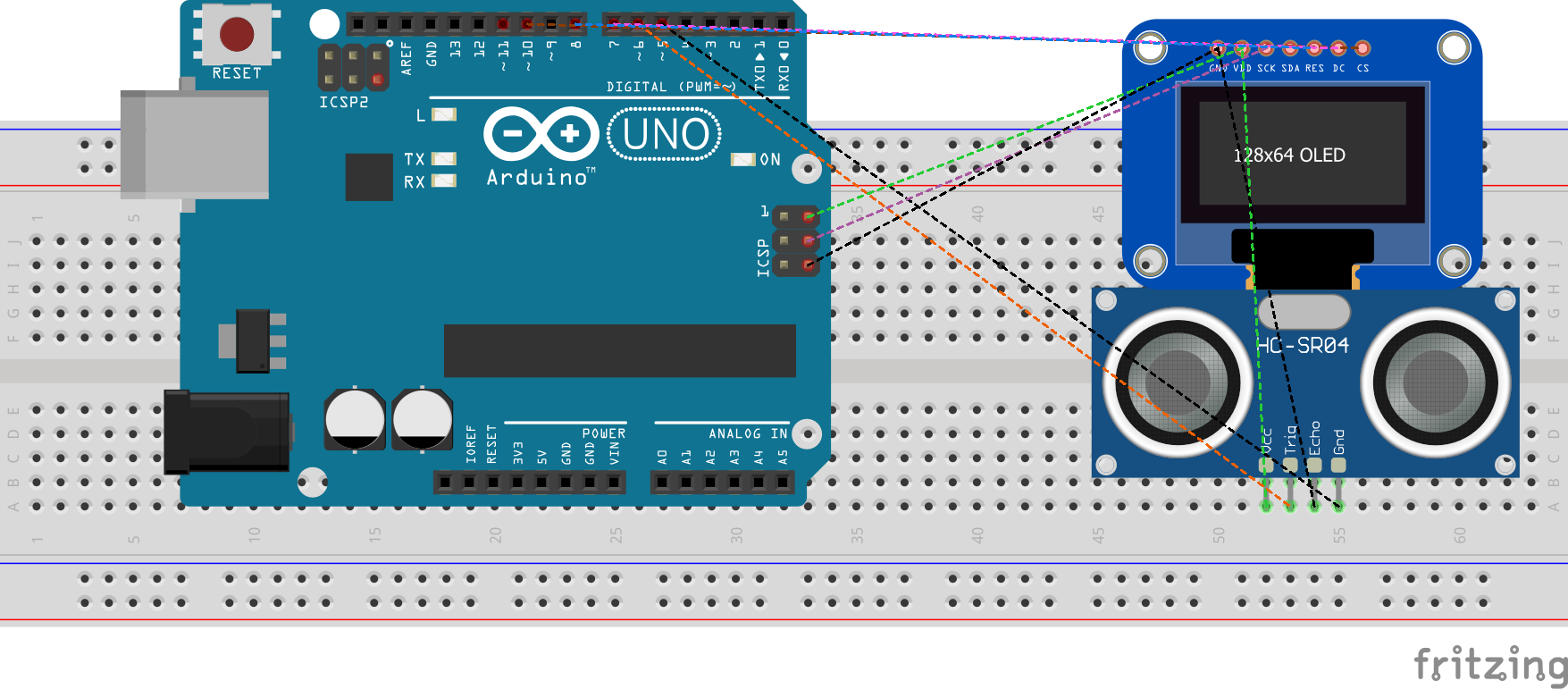
The WaveShare 1.5inch RGB OLED Display (SSD1351) uses a SSD1351 driver and the accompanying library provides the SPI (Serial Peripheral Interface) communication method, which requires specific wiring. Here's the general way to wire it up:
For the SPI connection, you’ll need to connect the OLED display to your Arduino as follows:
- VCC: Connect to Arduino 5V
- GND: Connect to Arduino GND
- DIN (MOSI): Connect to Arduino digital pin 11 (MOSI)
- CLK (SCK): Connect to Arduino digital pin 13 (SCK)
- CS: Connect to Arduino digital pin 10
- DC: Connect to Arduino digital pin 7
- RST: Connect to Arduino digital pin 8
*please make sure you install the correct driver - had a bit of a hiccup with the display until I realized my errors!* :, )
Once you’ve wired the OLED display, we’re ready to test it with some code!
I ended up going through a tutorial on creating the shapes (resourced below) and getting to learn how the coordinate system works with the pixels + dynamic graphics (gotta love loops). There are examples that iterates through a variety of drawing demonstrations, including: drawing lines, outlining and filling rectangles, circles, rounded rectangles, and triangles, rendering text with different styles, and drawing and animating bitmaps.
Here's the link for the tutorial: https://learn.adafruit.com/adafruit-gfx-graphics-library/graphics-primitives
Ultrasonic Sensor Setupyou’ll need to connect the sensor to your Arduino as follows:
- GND: Arduino GND
- Echo: Arduino digital pin 6
- TRIG: Arduino digital pin 5
- VCC: Arduino 5V
The overall schematic should look like this:
+5V         +---------+
      |          |         |
     OLED Display| Arduino |
     VCC  -------|    5V   |
                -|         |
     GND  -------|    GND  |
                -|         |
    DIN  ------- |   11    |
                -|         |
    CLK  ------- |   13    |
                -|         |
     CS  ------- |   10    |
                -|         |
     DC  ------- |    7    |
                -|         |
    RST  ------- |    8    |
                -|         |
                |         |
                +---------+
                  Ultrasonic
                    Sensor
     +5V        +---------+
      |         |         |
     TRIG  -----|    6   |
                -|         |
     ECHO  -----|    5    |
                -|         |
     GND  ----- |   GND   |
                |         |
+---------+Sensor Setup:
The ultrasonic sensor has two main components: a transmitter (trigger) and a receiver (echo). The trigger sends out a sound wave, and the echo receives the wave after it bounces off an object.
Measuring Distance:
To measure the distance, we need to send a pulse from the trigger, wait for the echo to receive the reflected pulse, and calculate the time it took for the round trip.
The formula to calculate the distance is:
Distance=Duration×Speed of Sound / 2
The speed of sound is approximately 343 meters per second or 0.034 cm per microsecond. We divide by 2 to account for the sound traveling to the object and back.
Mapping Distance to Eye Movement:
The distance measured by the ultrasonic sensor is mapped to a range of eye movement. For example, a distance of 0 to 200 cm might correspond to a range of -30 to 30 pixels for the eyes' position.
The map function in Arduino helps to convert the distance to the required range for eye movement:
eyeOffset=map(distance, 0, 200, −30, 30
Make sure the wiring + libraries are correctly installed, you should be able to run and execute the program successfully! :)
Helpful Resources
_ztBMuBhMHo.jpg?auto=compress%2Cformat&w=48&h=48&fit=fill&bg=ffffff)


Comments
Please log in or sign up to comment.